777 SERVICE MANUAL HYDRAULIC SYSTEM
Manitowoc Published 10-01-2012, Control # 045-08 2-27
2
±100 psi (6.9 bar) from that shown on the pressure
gauges.
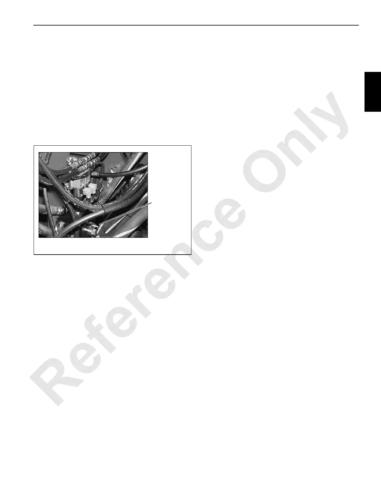
1. Check boom hoist charge pressure as follows:
a. Connect a 0 – 1,000 psi (0 – 69.0 bar) pressure
gauge to BOOM HOIST PUMP coupler at
transducer manifold (Figure 2-27).
b. Start engine and run it at low idle.
c. Turn boom hoist hot oil relief valve screw
(Figure 2-29) out until pressure on gauge stops
going down. This indicates boom hoist charge
pressure setting. Pressure must be 325 – 375 psi
(22.4 – 25.9 bar).
d. If proper pressure is not obtained, adjust charge
pressure relief valve at boom hoist pump. See
instructions in pump manufacturer’s manual.
e. Run engine at high idle. Pressure should not rise
above 450 psi (31.0 bar).
f. Run engine at low idle.
g. Turn hot oil relief valve screw (Figure 2-29) in until
pressure just starts to rise above boom hoist charge
pressure setting obtained in step 1c.
h. Continue to turn screw in until pressure is 25 psi (1.7
bar) higher than what was recorded in step 1g. This
is the hot oil relief valve setting.
i. Tighten nut on relief valve screw to lock adjustment.
j. Stop engine and remove gauge from transducer
manifold. Install dust cap over coupler.
2. Check charge pressure for remaining pumps, as follows:
a. Connect 0 – 1,000 psi (0 – 69.0 bar) pressure gauge
to coupler for desired pump at pressure sender
manifold (Figure 2-27).
b. Start engine and run it at low idle.
c. Note and record gauge reading. Gauge should read
325 – 375 psi (22.4 – 25.9 bar) and not exceed 450
psi (31.0 bar) at high idle.
If proper pressure is not obtained, adjust charge
pressure relief valve for corresponding pump. See
instructions in pump manufacturer’s manual.
d. Stop engine and remove gauge from coupler at
pressure sender manifold (Figure 2-27). Install dust
cap over coupler.
Accessory System Pressure Checks
1. Connect a 0 – 1,000 psi (0 – 69.0 bar) pressure gauge to
coupler at accessory system relief valve (Figure 2-26).
2. Start and run engine at low idle. Gauge should read 500
psi (34.5 bar) maximum. This is accessory system
unload pressure.
3. Remove gauge installed in step 1 and replace it with a 0
– 5,000 psi (0 – 344.8 bar) pressure gauge.
4. Using controls on carbody, fully retract any carbody jack
to stall accessory system relief valve. Gauge should
read approximately 3,000 psi (206.9 bar).
5. If proper pressure is not obtained, adjust accessory
system relief valve to obtain 2,900 – 3,100 psi (200.0 –
213.7 bar) pressure setting (turn relief valve screw in to
increase pressure or out to decrease pressure). This is
the accessory system pressure setting.
6. Tighten nut on screw to lock adjustment.
7. Stop engine and remove gauge from coupler. Install dust
cap over coupler.
P576a
Boom Hoist Hot
Oil Relief Valve
Between Rear Drum
and Hydraulic Tank
FIGURE 2-29
 Loading...


