Manitowoc Published 10-01-2012, Control # 045-08 3-3
777 SERVICE MANUAL ELECTRIC SYSTEM
3
TEST VOLTAGES
This section contains test voltages sorted into three
categories:
Pin Identification................................................. 3-4
Wire Identification................................................3-9
Description Identification ...................................3-14
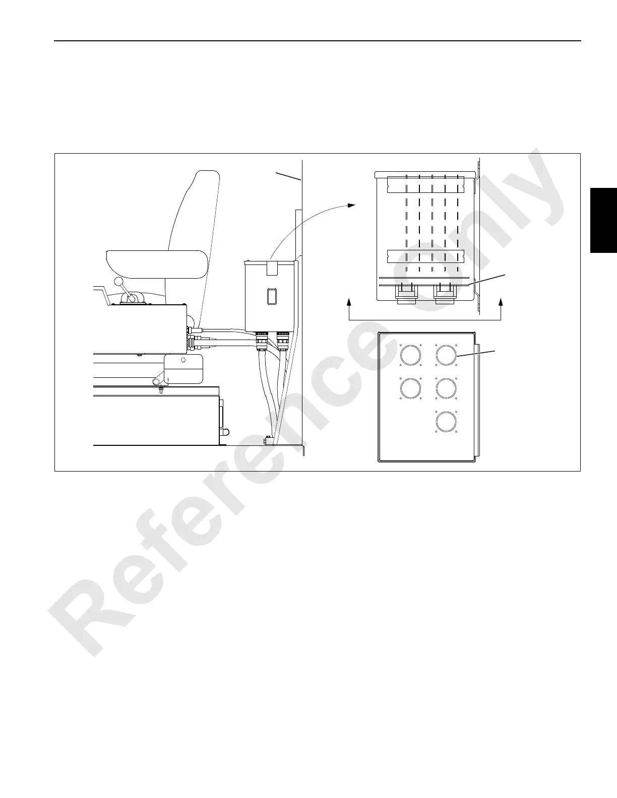
Controller Board Layout
The board locations in the programmable controller are
shown below.
E
D
B
C
A
CPU BOARD
I/O BOARD 1
I/O BOARD 2
I/O BOARD 3
I/O BOARD 4
Rear Cab
Wall
Mother
Board 1
Cable
Connector
A1105
FIGURE 3-1

 Loading...


