INTRODUCTION 777 SERVICE MANUAL
1-36 Published 10-01-2012, Control # 045-08
SWING SYSTEM
See Figures 1-22 and 1-23 for following procedures.
In order for normal swing operation to occur, the rear load
drum charge pressure must be about 232 psi (16 bar). If the
charge pressure drops below this amount, the hydraulic
brake will begin to partially or fully apply.
After startup, swing park switch, located on the right console
in the operator’s cab, is placed in the off position, closing the
circuit to swing park brake hydraulic solenoid HS7. Swing
brake control valve is shifted against its spring, opening a
path for oil supply from the rear load drum charge pump to
flow through to swing park brake. The pressure compresses
the brake spring to release the brake.
When swing park switch is placed in the on position, the
circuit to swing brake hydraulic solenoid HS7 is opened.
Spring force shifts swing brake valve, closes the path of oil
supply from the rear load drum charge pump and the
pressure in swing park brake is vented to tank so the brake
spring-applies.
Swing holding brake switch, located on the side of swing
control handle, provides the operator with a means of
preventing swing movement. Depressing switch opens a
circuit to the PC. The PC then opens this circuit to the swing
pump EDC, which places swing pump in neutral and applies
the brake by closing the circuit to swing park brake hydraulic
solenoid HS7.
To prevent damage to the swing system components, swing
holding brake switch should only be applied when the
machine is in a stand-still position. When in a swinging
motion, the preferred method of stopping or slowing the
crane is to move swing control handle beyond center in the
opposite direction of movement. This action causes a
hydrodynamic slowing of the rotating bed.
Swing Lock
See Figures 1-22 and 1-24 for following procedures.
The swing lock mechanism is located between the swing
motor and swing brake on the swing motor planetary.
When the swing lock switch, located on the right console in
the operator’s cab, is placed in the disengaged position, the
circuit to swing lock disengage hydraulic solenoid HS15
closes, and the circuit to swing lock engage hydraulic
solenoid HS14 opens. Swing lock valve shifts, opening a
path for oil supply from the rear load drum charge pump to
extend side of the swing lock mechanism piston while oil
from the retract side of the swing lock piston exhaust to tank
through swing lock valve.
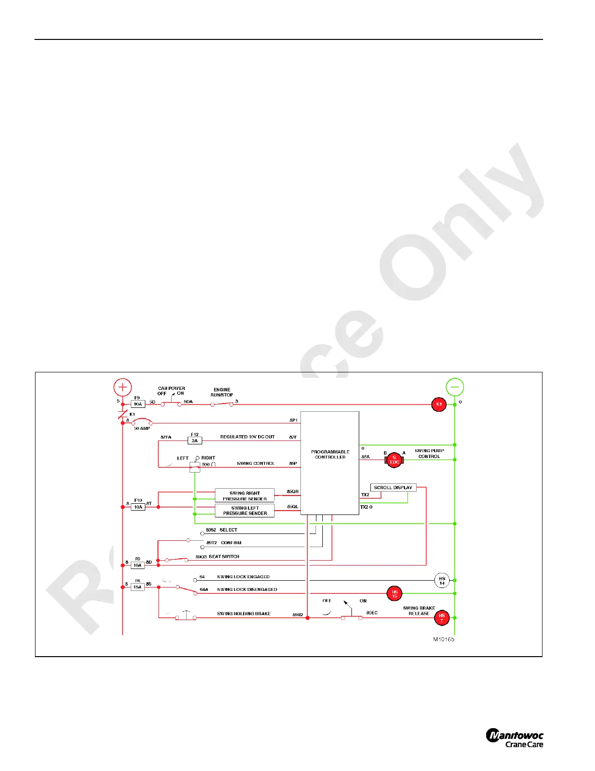
FIGURE 1-22

 Loading...


