TROUBLESHOOTING 777 SERVICE MANUAL
10-48 Published 10-01-2012, Control # 045-08
Test 18 – Testing for Pump and Motor Leakage
Testing for pump and motor leakage requires a 3,000 psi
(207 bar) in line flow meter with minimum flow rated capacity
of 10 gpm. Flow meters can be ordered from Manitowoc
Cranes, Inc.
Flow from individual pump and motor drains depend on
several operational factors and settings. Acceptable leakage
is based on the combined case flow of the pump and motor.
The combined case flow from load drum pump and motor
should be equal to a charge pump flow of 8.9 gpm per 1,000
rpm of the engine. The combined case flow from swing or
travel pump and motor should be equal to a charge pump
flow of 4.8 gpm per 1,000 rpm of the engine.
For load drum or travel motor begin by connecting flow meter
between motor case drain hose and port L1 or L2 (use
highest port for testing). To test swing motor, connect the
flow meter between motor case drain hose and case outlet 1.
(See Test 10 for location of motor test ports.) With engine
running at 1,000 rpm, measure motor flow rate. Swing and
travel motors should not exceed 1 gpm case flow at neutral.
At heavier loads and higher rpm, case flow may increase to 4
or 5 gpm. Record results at neutral and reconnect motor
case drain hose to motor port. The difference between circuit
charge pump flow and case flow at neutral is the acceptable
pump case flow at neutral for circuit being tested.
Connect flow meter between pump case drain hose and
pump port L1 or L2 (use highest port for testing). (See Test 9
for location of or pump test ports.) With engine running at
1,000 rpm, measure pump flow rate at neutral and compare
to calculated acceptable pump case flow.
Changes from normal or major changes with increasing
system pressure more than ±1 gpm are indicators or pump
or motor problems.
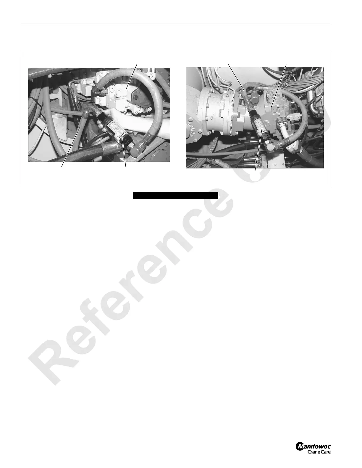
Item Description
1 In line flow meter
2 Pump case drain hose
3Pump
4 Motor case drain hose
5 Motor
FIGURE 10-23
P697
P697
2
1
3
5
4
1

 Loading...


