Manitowoc Published 10-01-2012, Control # 045-08 1-43
777 SERVICE MANUAL INTRODUCTION
1
LOAD DRUM (FULL POWER MODE)
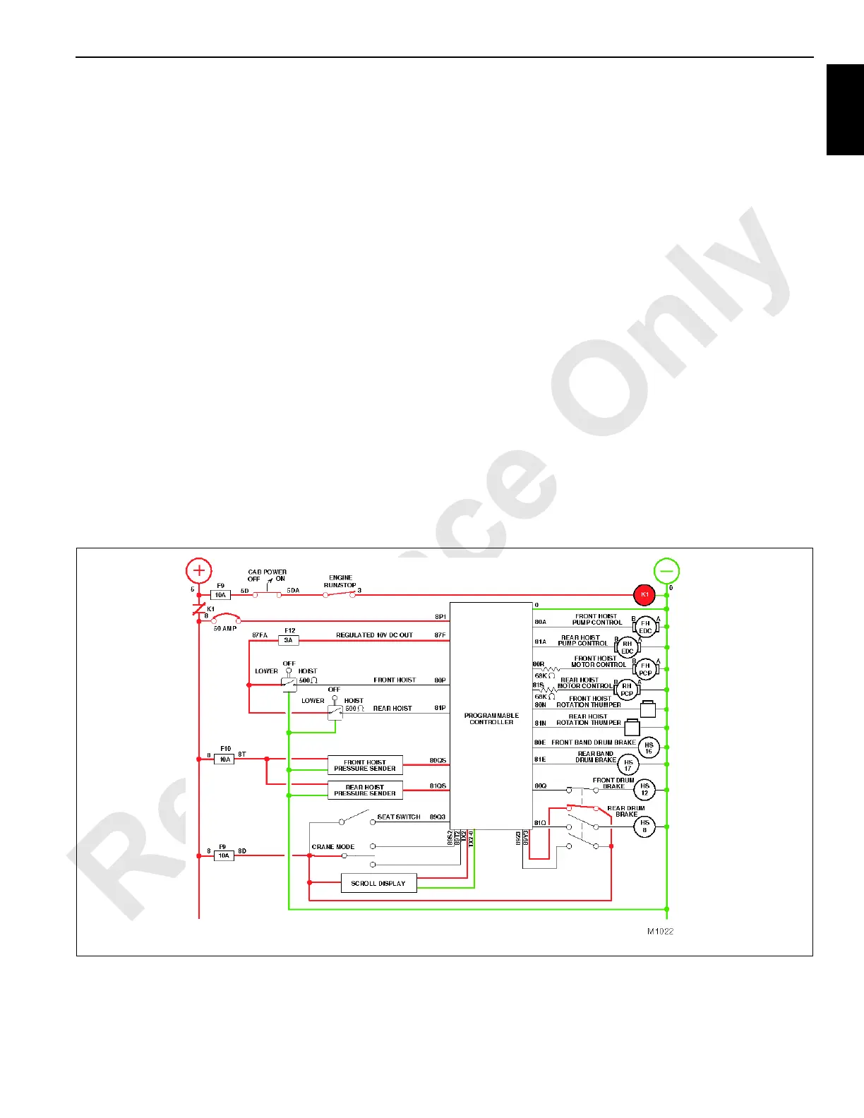
See Figures 1-29, 1-30, and 1-31 for following procedures.
The following description is for the front drum without
optional clutch assembly while operating in full power mode.
Function of the rear drum in full power mode is identical. The
clutch assembly is described in the free fall mode section of
this manual.
With free fall, the free fall switch must be closed for brakes to
release and pump to go on stroke.
Front and rear hoist control handles are located adjacent to
one another on right console in the operator’s cab. The
position of these handles may be interchanged depending
on the functional orientation of the front and rear drums.
The hydraulic connection between front hoist pump and front
hoist motor forms a simple closed-loop circuit. Make-up oil
from front hoist charge pump replaces oil in the system that
is primarily displaced due to internal leakage of the pump
and motor assemblies.
If front drum park switch located on the front console in the
operator’s cab, is placed in the ON position, the front hoist
control handle circuit to the PC opens and does not complete
the circuit from the PC to front drum disc brake hydraulic
solenoid HS12 and band brake solenoid HS16. Because
these circuits are open, front drum hydraulic disc and band
brakes remain applied and front hoist pump does not stroke
in response to movement of front hoist control handle.
When performing liftcrane, clamshell, or luffing operations in
full power mode, the brake function employs two
independent brake systems, band brake and hydraulic disc
brake, each hydraulically actuated.
The hydraulic disc brake is spring applied/pressure released
and is controlled automatically by the PC in conjunction with
movement of front drum control handle. Release of brake
during operation of the front drum is sourced from 350 psi
(24 bar) charge pressure pump of the closed-loop circuit.
When releasing brake, charge pressure is directed into
brake valve through HS12. If the charge pressure drops to
below 295 psi (20 bar), hydraulic brake application begins; if
the pressure continues to drop to approximately 220 psi (15
bar) or lower, the brake is fully applied.
The band brake is actuated when heavy duty coil spring is
decompressed and the brake band applies a holding
resistance against the drum flange. The PC automatically
energizes the band brake hydraulic solenoid HS16 opening
a path of flow from auxiliary pump to band brake release
cylinder. The brake cylinder piston extends, causing the
heavy duty coil spring to compress, releasing the holding
resistance applied to the drum flange.
FIGURE 1-29

 Loading...


