ELECTRIC SYSTEM 777 SERVICE MANUAL
3-24 Published 10-01-2012, Control # 045-08
CRANE DIAGNOSTICS
To activate the diagnostic display screens, depress the limit
bypass switch and scroll up. Once this step is performed,
you can scroll up and down through the diagnostic screens in
addition to the normal operating screens. To deactivate the
diagnostic screens, depress the limit bypass switch and
scroll down. The normal operating screens will remain
active.
The diagnostic display provides information about the status
of all main crane components as well as the controller inputs
and outputs during operation. There are a total of twelve
diagnostic screens:
• Six which display information about particular crane
functions — DRUMS 1, 2, and 8, BHST (Boom Hoist),
SWING, and TRACK.
• Three which display information about digital inputs and
outputs — D1 (outputs from crane controller), D2 (inputs
to crane controller), and A1 (handle/pedal inputs to
crane controller).
• Three which display controller programming information
— A2, A3, and D3. These screens are for factory use
only, and are not shown in this section.
See Figures 3-7 – 3-9 for drum, handle/pedal, and pump
identification.
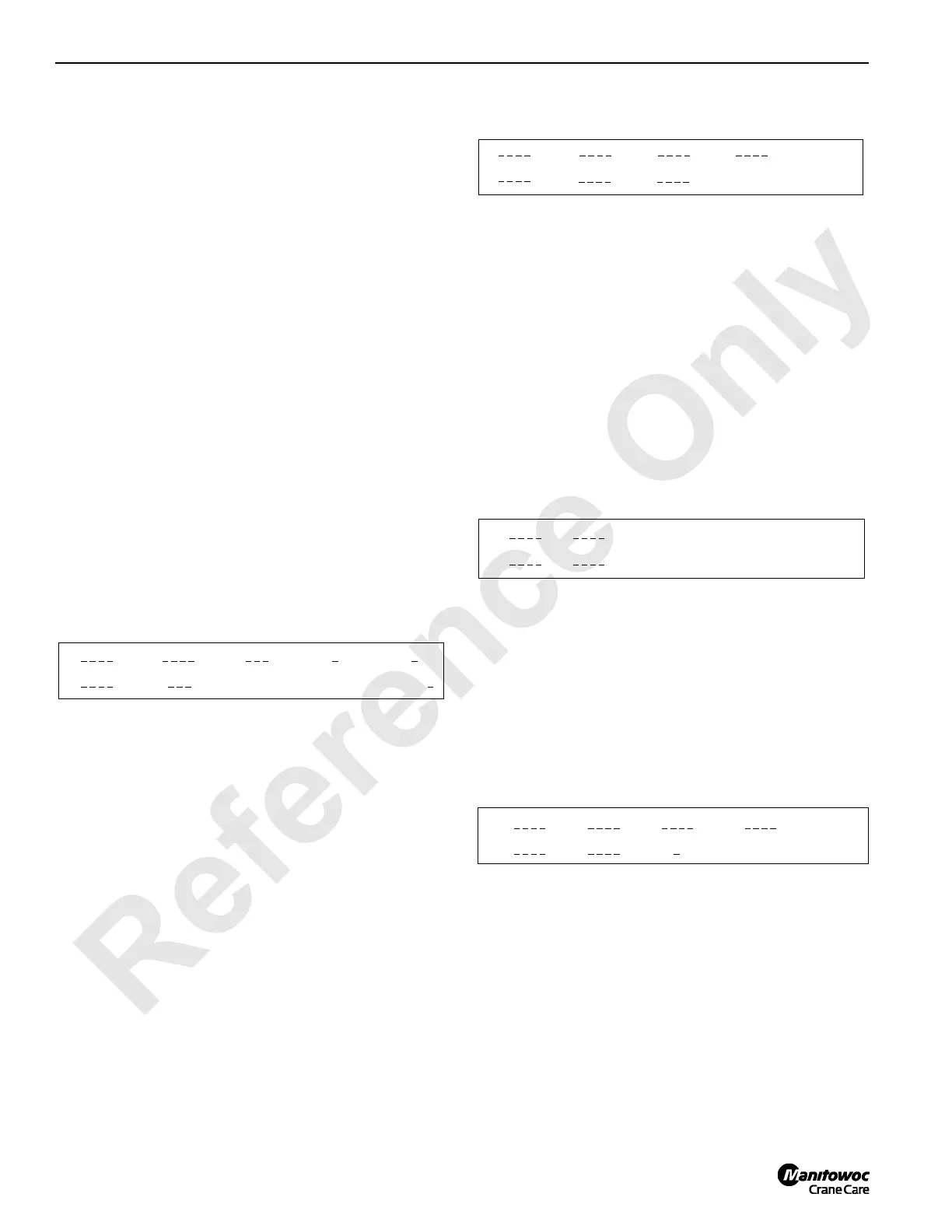
Drum 1, 2, and 8
1. Handle command in percent from neutral (+ raise, –
lower)*
2. Pump command in percent from neutral (+ raise, –
lower).
3. Motor command in percent (0% max. displacement,
100% min. displacement).
4. Parking brake command (1 release, 0 engage).
5. Clutch command (1 release, 0 engage) (applies only to
drums with free fall, otherwise has no meaning).
6. Measured pump pressure (port A) in psi.
7. Measured drum speed in rpm (+ raise, – lower).
X Corresponding drum number appears.
*For certain operating conditions handle command can be
set to neutral by the controller even if handle is not in neutral.
BHST (Boom Hoist)
1. Handle command in percent from neutral (+ up, – down)
2. Pump command in percent from neutral (+ up, – down)
3. Measured pump pressure (up) in psi
4. Measured cylinder pressure (up) in psi
5. Port 0 count – right cylinder position (+ retract, – extend)
6. Port 1 count – left cylinder position (+ retract, – extend)
7. Boom valves (1 raise holding valve on, 2 lower holding
valve on, 3 both holding valves on, 4 pump enable valve
on, 5 pump enable valve and raise holding valve on, 6
pump enable valve and lower holding valve on, 7 pump
enable valve and both holding valves on)
Swing
1. Handle command in percent from neutral (+ right, –
left)*.
2. Pump command in percent from neutral (+ right, – left)
3. Measured pump pressure swing right (port A) in psi.
4. Measured pump pressure swing left (port B) in psi.
*For certain operating conditions handle command can be
set to neutral by the controller even if handle is not in neutral.
Track
1. Right handle/pedal command in percent from neutral (+
forward, – backward)*.
2. Left handle/pedal command in percent from neutral (+
forward, – backward)*.
3. Right pump command in percent from neutral (+
forward, – backward).
4. Left pump command in percent from neutral (+ forward,
– backward).
5. Measured system pressure right track in psi.
6. Measured system pressure left track in psi.
1
6
2
7
3
DRUM
4 5
X
1
5
23
BHST
4
6 7
1
3
2
4
SWING
1
5
2
6
3
7
4
TRACK

 Loading...


