Manitowoc Published 10-01-2012, Control # 045-08 4-19
777 SERVICE MANUAL BOOM
4
11. Whenever possible, welding shall be done in the
horizontal position.
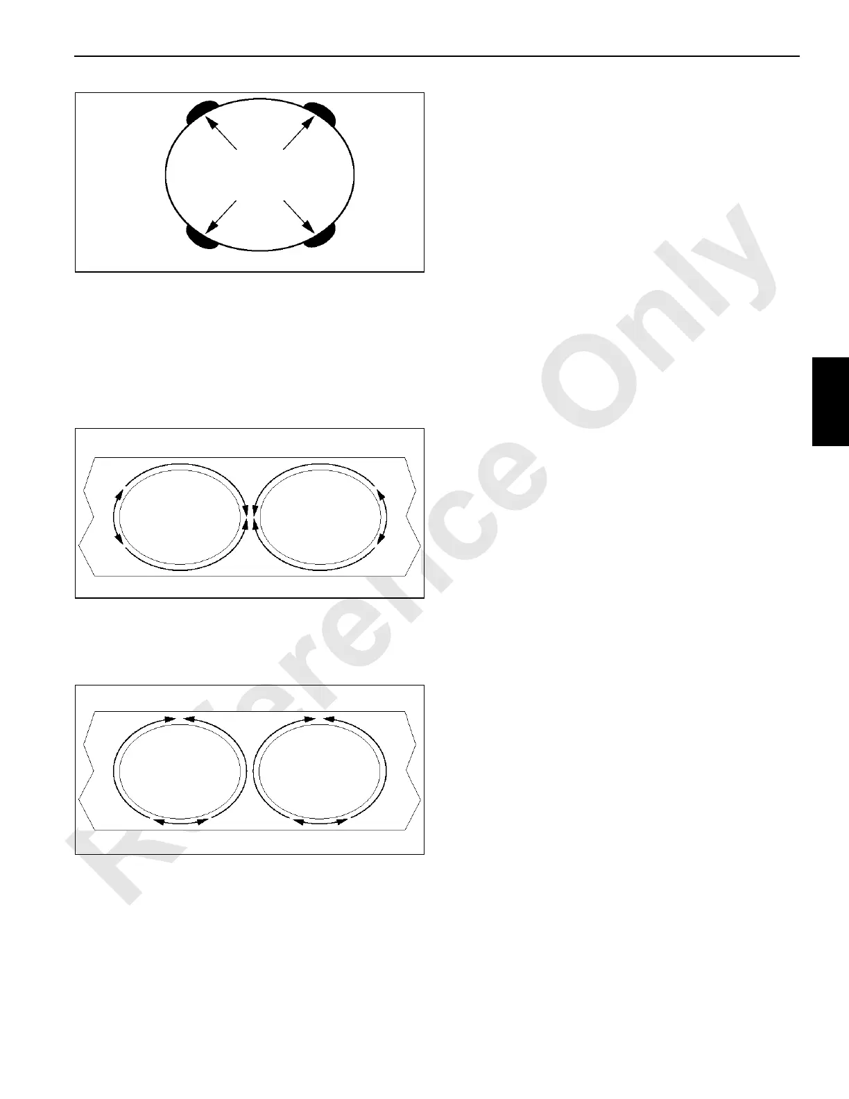
a. Use the following sequence for horizontal and
overhead welding. The weld pass should start at the
heel of the lacing and end on the toe (Figure 4-20).
Pass placement will differ from the horizontal and
the overhead position.
NOTE See Figure 4-24 for pass placement.
b. Use the following sequence for vertical welding. The
weld pass shall start at the 6:00 O’clock position and
end at the 12:00 O’clock position (Figure 4-21).
NOTE See Figure 4-24 for pass placement.
Weld profiles shall be smooth and blend gradually into
the base metal. Undercut shall not exceed 0.010 in (0.25
mm) deep on any lacing-to-chord joint. No piping
porosity is allowed in any weld repairs.
12. Use the following preheat and interpass temperatures:
• Minimum of 150°F (66° C)
• Maximum of 350°F (177° C)
NOTE All welders are required to monitor minimum and
maximum interpass temperatures by use of
temperature sticks. Apply heat evenly to avoid spot
heating any one area.
13. Use the weld size dimensions recorded during Lacing
Replacement step 1 on page page 4-18 to determine the
weld size for the replacement lacings. Refer to
Figure 4-24 for weld size and pass placement. The
finished weld must match the profile and size of the
corresponding lacings.
No excessive weaving is allowed. The Maximum bead
width is 5/16 in (8 mm).
14. Allow all finished welds to cool slowly to ambient
temperature.
15. Visually inspect for proper workmanship and correct
weld size. M.T. or P.T. inspect for soundness 48 hours
after welding is completed.
Do not use the lattice section during the 48 hour wait
period.
NOTE The 48 hour wait period prior to the final M.T. or P.T.
inspection can be waived if welding was performed
by a qualified Manitowoc representative.
Any welder that has taken and passed
Manitowoc’s Boom Lacing Replacement Class
is considered qualified by Manitowoc
.
Manitowoc recommends the N.D.T personnel be
certified to A.S.N.T. Level ll.
16. Prime and paint the welded area.
17. Send all completed inspection reports to Manitowoc
Crane Care. If possible, digital photographs should be
taken and submitted with the inspection reports.
End Lacing Replacement
End Lacings are the lacings that are closest to the
connectors and run perpendicular to the chords as shown in
Figure 4-22.
The end lacings hold the back-to-back and diagonal
dimensions of the chords and connectors. It is critical that the
original manufacturing connector tolerance be maintained.
Removing these lacings without properly bracing the lattice
section will make it extremely difficult to pin the repaired
section to another section.
Only one lacing should be replaced at any given time to help
hold the dimensions of the chords and connectors. The
procedure for removing the end lacings from an insert is
different from the procedure for a top or butt lattice section.
FIGURE 4-19
Tack Weld these Locations Only
Tack Welds Must be
1-1/2 in (38,1 mm) Long
FIGURE 4-20
Horizontal and Overhead Welding Sequence
FIGURE 4-21
Vertical Welding Sequence

 Loading...


