Manitowoc Published 10-01-2012, Control # 045-08 10-51
777 SERVICE MANUAL TROUBLESHOOTING
10
Test 21 – Adjusting the Lower Accessory Relief Valve
Connect 0 to 1,000 psi (0 to 69 bar) pressure gauge to
coupler at accessory system relief valve.
Start and run engine at low idle. This is accessory system
unload pressure.
Remove 0 to 1,000 gauge and install a 0 to 5,000 psi (0 to
345 bar) pressure gauge to coupler at accessory system
relief valve. Using controls on carbody, fully retract any
carbody jack to stall accessory system relief valve. Gauge
should read approximately 3,000 psi (207 bar).
If correct pressure is not obtained, adjust accessory system
relief valve to obtain 2,900 to 3,100 psi (200 to 214 bar)
pressure. Turn relief valve screw in to increase pressure or
out to decrease pressure. This is the accessory system
pressure setting.
Tighten nut on screw to lock adjustment.
Stop engine and remove gauge from coupler. Install duct cap
over coupler.
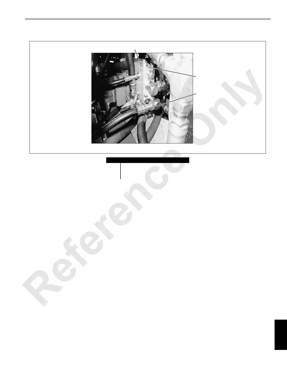
Item Description
1 Accessory System Relief Valve
2 Accessory System Pilot Check Valve
3 Accessory System Gauge Coupler
FIGURE 10-26
P577
Under Left Side of Pumps
2
3
1
 Loading...


