Manitowoc Published 10-01-2012, Control # 045-08 6-1
777 SERVICE MANUAL SWING
6
SECTION 6
SWING
MANUAL RELEASE OF SWING BRAKE AND
LOCK
The hydraulic swing brake and hydraulic swing lock must be
released when the swing planetary is removed and
reinstalled to allow alignment of the gear teeth in the swing
shaft with the teeth in the ring gear.
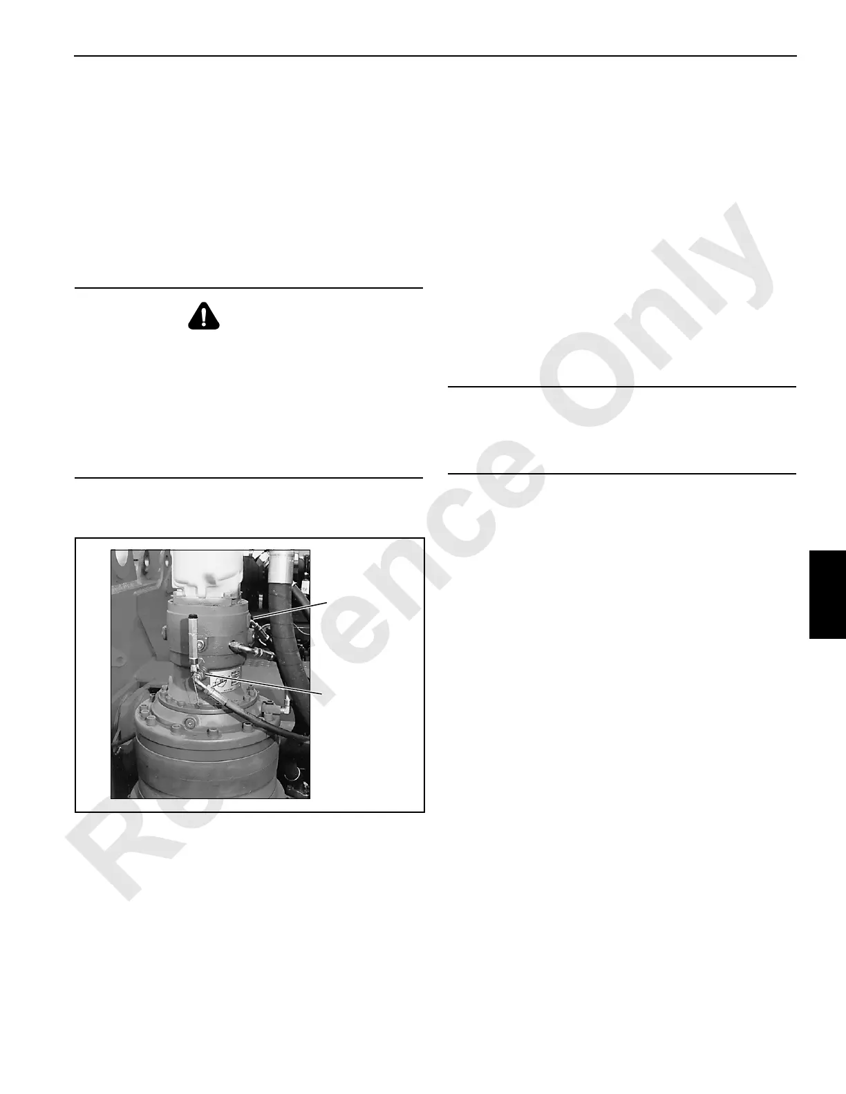
Figure 6-1 shows the swing planetary and the type of swing
lock.
Manual Release Procedure
Hydraulic hand pumps with pressure gauges are needed to
manually release the swing brake and swing lock.
1. Disconnect hoses from fitting at brake release port and,
if equipped, at swing lock OUT port.
2. Attach hand pump to each port — brake release and
swing lock OUT.
3. Pressurize brake and swing lock to 350 psi (24 bar).
4. Proceed to remove or install swing planetary.
5. Relieve pressure and remove hand pumps.
WARNING
Unexpected Crane Movement!
Crane can swing suddenly when swing brake is released.
Before releasing swing brake, secure crane by lower
boom onto blocking at ground level to prevent sudden
uncontrolled swinging.
The procedure given in this section is for servicing
purposes only. Swing brake and swing lock must be fully
operational when operating crane.
FIGURE 6-1
P899
Brake Release
Port
(06 ORS Fitting)
Swing Lock
OUT Port with
Inside
Planetary
(06 ORS
Fitting)
CAUTION
Avoid damage to parts!
Do not exceed 350 psi (24 bar) pressure when releasing
swing brake or swing lock.

 Loading...


