Manitowoc Published 10-01-2012, Control # 045-08 5-13
777 SERVICE MANUAL HOISTS
5
4. Cranes with free fall, check each foot pedal latch and
latch bar for wear (Figure 5-9). Pedal latch must
securely hold pedal down in fully applied position.
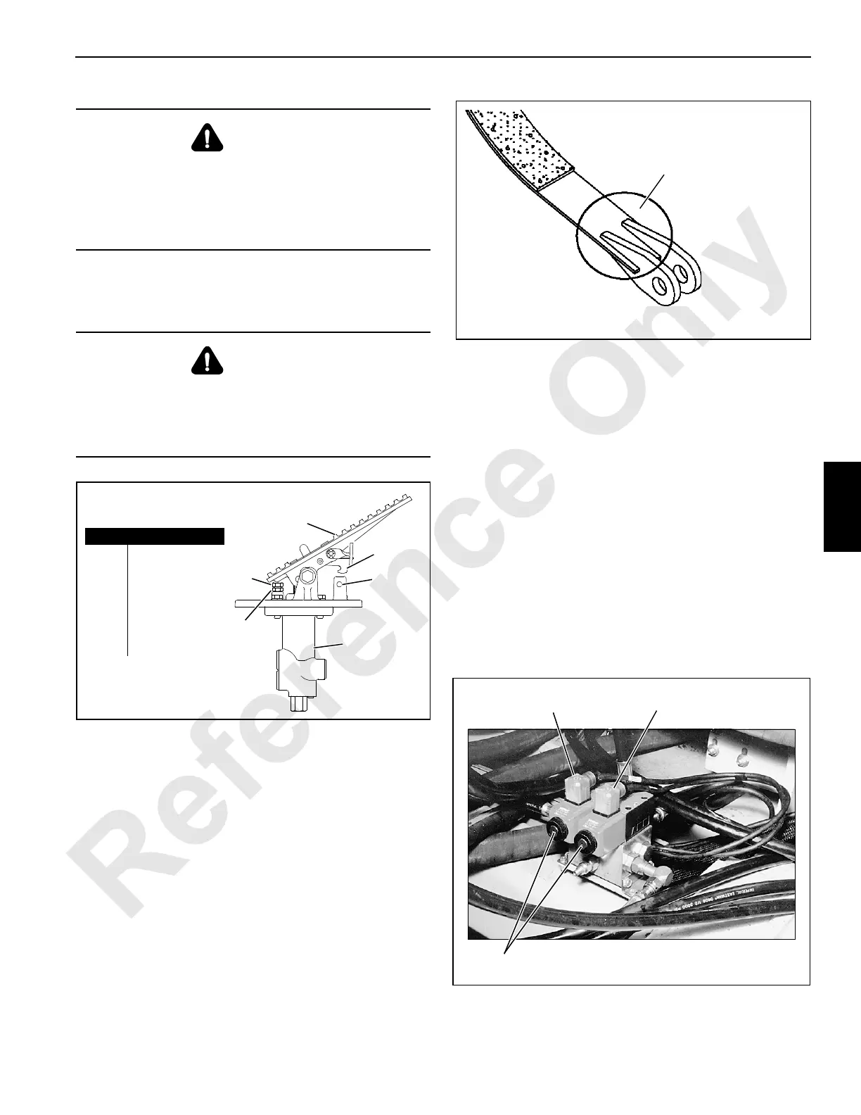
5. Thoroughly inspected the brake bands for cracks and
corrosion when the bands are removed for relining. This
inspection procedure also applies to band assemblies
that are received in exchange for bands that were
removed for relining.
The inspection method shall include non-destructive
testing — magnetic particle (MT) or ultrasound (UT).
The primary area to inspect is the dead-end attachment
area on the band (see Figure 1).
If there is evidence of cracks or 10% reduction in area
due to corrosion, destroy and discard the band and
replace with it a new band or a band that has passed
non-destructive test/inspection. Contact your Manitowoc
dealer for brake band thickness. Please have the band
part number available at the time of the request.
Brake Adjustment
To prevent injury when adjusting brakes, operator and
adjuster must observe all safety precautions following
Safety heading.
Brake adjustment requires corresponding load drum to be in
STANDARD mode with FREE FALL OFF (optional). Detailed
procedures for selecting operating modes are in Operating
Controls in Section 3 of Crane Operator’s Manual.
The actuator must be disconnected from brake band to
adjust brake. The actuator’s total weight is 260 lb (118 kg). A
means of supporting the actuator when it is
disconnected must be provided by crane owner/user.
To prevent drum control handle from having to be operated
(load remains on ground), manual override in the
corresponding brake solenoid valve (Figure 5-11) will be
used to apply and release drum brake as described in Brake
Adjustment step 5.
WARNING
Falling Load Hazard!
Do not operate crane if leading edge of spring sleeve is
past line at end of safe working range on adjustment
indicator. Brake will not provide proper braking torque,
and load may lower through brake.
WARNING
Falling Load Hazard!
Do not operate crane if any pedal latch is not operating
properly. Pedal could unlatch, allowing a suspended load
to fall.
FIGURE 5-9
A963
Item Description
1Jam Nut
2 Free-Play
Adjusting Screw
3 Pedal
4Latch
5 Latch Bar
6Valve
1
2
3
4
5
6
FIGURE 5-10
Primary Inspection Area
FIGURE 5-11
P473
Hole
(override pin inside)
Right Side of Crane
Rear Drum Brake
Solenoid Valve
Front Drum Brake
Solenoid Valve
Behind Rear Drum

 Loading...


