TROUBLESHOOTING 777 SERVICE MANUAL
10-34 Published 10-01-2012, Control # 045-08
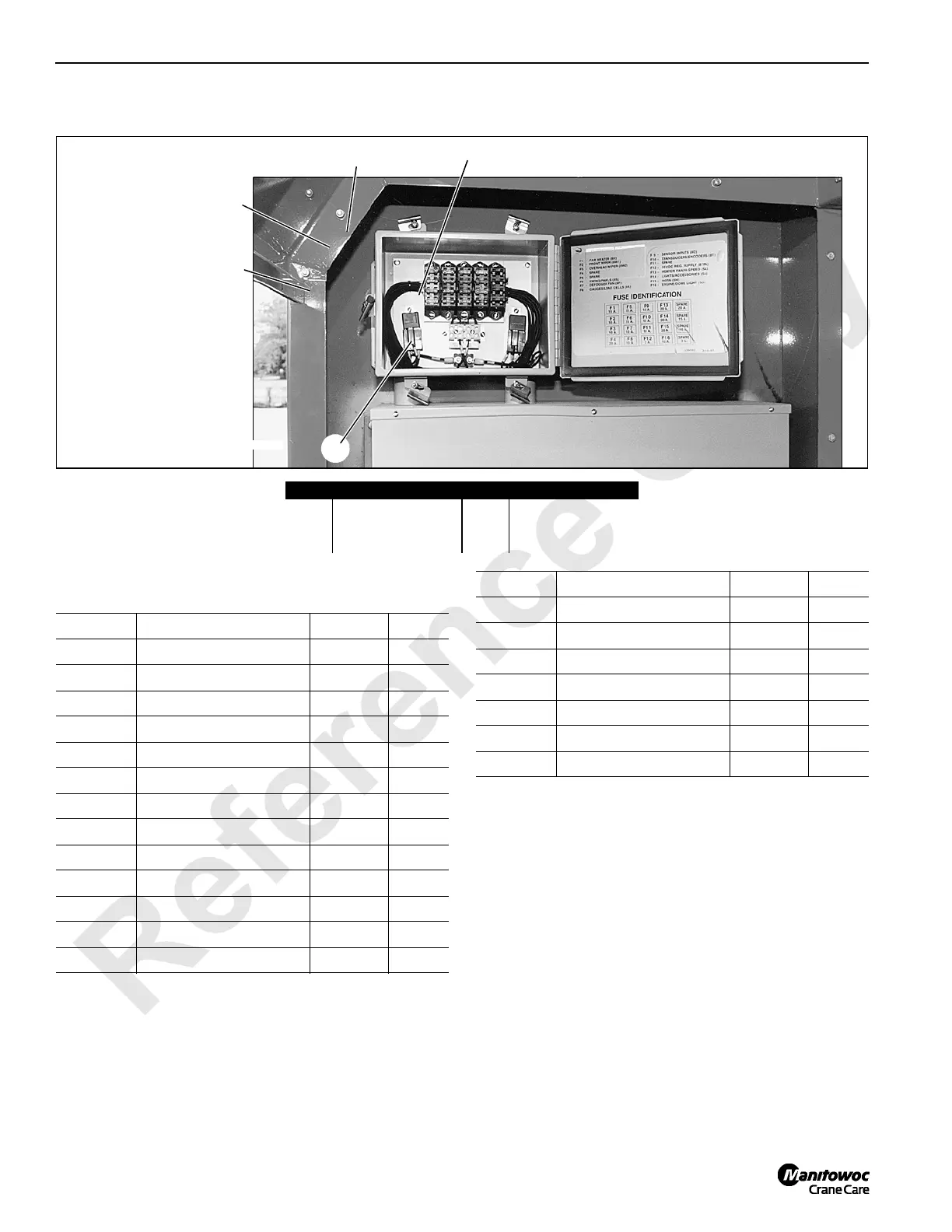
Test 6 – Testing for Voltage at the Fuse Box
Table 10-1
Fuse Identification
Use a digital multimeter for testing voltage at the fuse box.
To test for volts DC at any given fuse socket, place the
positive probe on either of the metal fuse contacts and the
negative probe on the grounded fuse box chassis. Repeat
this procedure using the other fuse contact as a test point.
Note all fuse sockets except F12 (3A, 10V) should yield 12
volts DC.
To determine if relay K1 is fully functional, ground the fuse
box chassis and verify 12 volts DC exist at relay wire 8 when
the relay is energized. Also verify 12 volts at relay wire 5.
Item Description Item Description
1 Fuse block 4 Fuse box chassis
2 Metal fuse contact 5 K2 power output
3 K1 cab power relay
2
1
P580
3
4
5
FIGURE 10-8
Fuse No. Function Wire No. Amps
F1 Cab Heater 8H 15
F2 Front Wiper 8W1 10
F3 Overhead Wiper 8W2 10
F4 --------------- ----- 20
F5 --------------- ----- 15
F6 Swing/Pawls 8S 15
F7 Defogger Fan 8F 10
F8 Gauges/Accessories 8A 10
F9 Sensor Inputs 8D 10
F10 Transducers/Encoders 8T 10
F11 Spare ------ 10
F12 10VDC Reg. Supply 87FA 3
F13 Lights/Accessories 5A 20
F14 Lights/Accessories 5A 20
F15 Horn 5H 20
F16 Engine/Dome Light 5D 10
Spare --------------- ------ 20
Spare --------------- ------ 15
Spare --------------- ------ 10
Spare --------------- ------ 3
Fuse No. Function Wire No. Amps

 Loading...


