Manitowoc Published 10-01-2012, Control # 045-08 1-65
777 SERVICE MANUAL INTRODUCTION
1
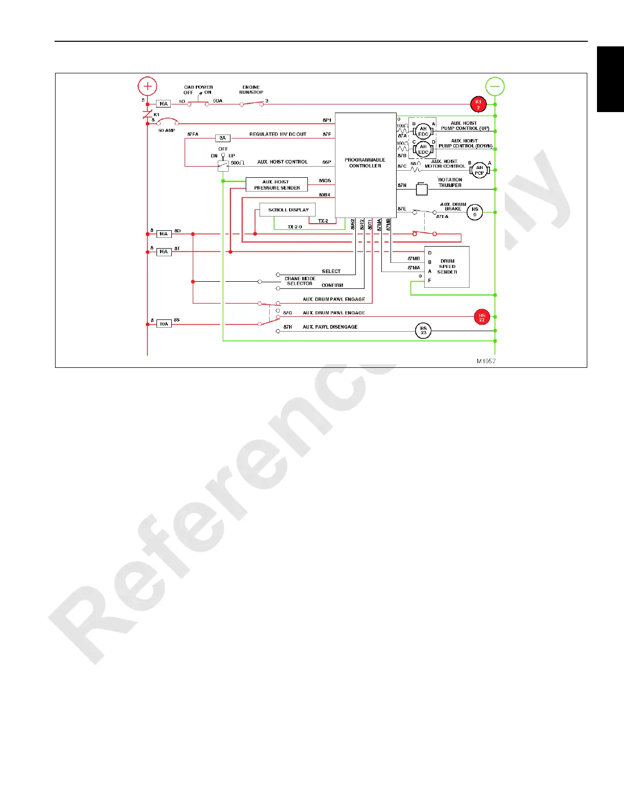
Auxiliary Hoist Rotation Indicator
Whenever the auxiliary drum rotates, auxiliary drum speed
sender completes a circuit to the PC that activates rotation
thumper in control handle. This causes rotation thumper to
move up and down with a varying frequency that conveys the
rotational speed of the drum to the operator.
Auxiliary Drum Pawl System
The ratchet and pawl mechanism provides a positive means
of locking the position of auxiliary drum. The pawl system
operates independently and is controlled by a 2-position
double throw switch located on the front console.
The pawl should be used to maintain loadline locations,
especially when the crane is in the park position or left
unattended. Likewise, the front and rear drums should be
used for locking the corresponding drum in position when not
in use. The auxiliary drum pawl when selected to be
operated must be disengaged before it can be rotated
downward because the PC will not command release of the
brake by energizing HS9 and command the auxiliary pump
EDC to stroke the auxiliary pump in the down direction.
Should the pawl switch be accidentally activated, the PC
program opens the circuits to the auxiliary drum brakes. The
auxiliary drum brakes then apply.
Auxiliary Hoist Off
See Figures 1-46 and 1-47 for following procedures.
When auxiliary hoist control handle, located on the right
console in the operator’s cab, is in the off position, the handle
neutral switch is open, the PC receives no voltage from the
handle, and the PC opens the circuits to the auxiliary hoist
pump EDC, auxiliary hoist motor PCP valve, and auxiliary
drum brake hydraulic solenoid HS9. Because these circuits
are open, auxiliary hoist pump does not stroke, auxiliary
hoist motor remains at low speed, and auxiliary drum park
brake remains spring-applied to prevent the auxiliary drum
from turning.
Auxiliary Hoist Raise
See Figures 1-48 and 1-49 for following procedures.
When control handle is pulled back for up operation, the
handle neutral switch closes, completing a regulated voltage
circuit from the handle potentiometer to the PC. The PC
interprets the signal for speed and direction and closes
regulated voltage circuits to the auxiliary hoist pump (up)
EDC, auxiliary hoist motor PCP and auxiliary drum park
brake hydraulic solenoid HS9. These circuits will close only if
the auxiliary drum park switch is off, applicable operating
limit switches are closed, and no system or operating faults
are present.
PC programming requires auxiliary hoist pump to stroke
before the auxiliary drum park brake is released. This
ensures adequate pressure is present to hold the load after
full release of the park brake. The regulated voltage to the
auxiliary hoist pump (up) EDC tilts the pump swashplate to
FIGURE 1-47

 Loading...


