Manitowoc Published 10-01-2012, Control # 045-08 1-67
777 SERVICE MANUAL INTRODUCTION
1
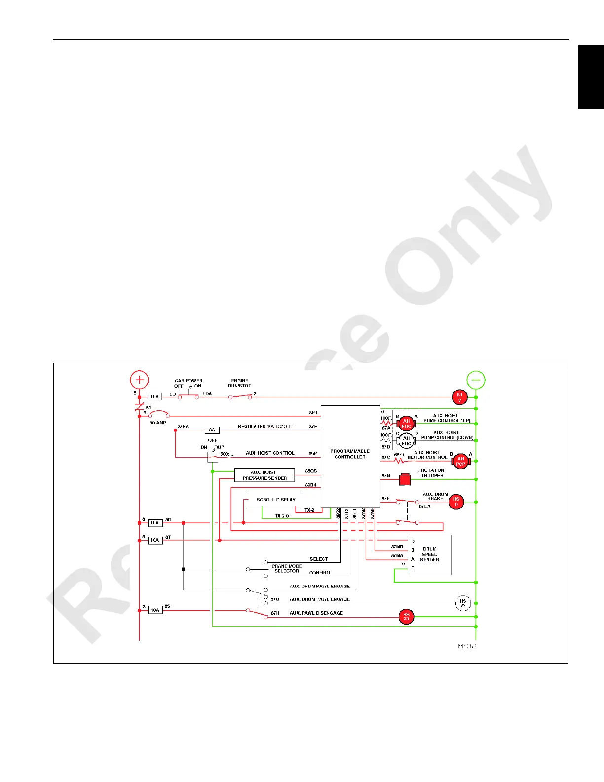
Auxiliary hoist pressure sender supplies the PC with
pressure development data that the PC compares to the
memorized holding pressure of the auxiliary hoist. When
adequate pressure is available, the PC energizes HS9 to
shift brake valve, releasing the drum brake while de-
energizing the (up) EDC and energizing the (down) EDC.
The regulated voltage to the auxiliary hoist pump (down)
EDC then causes the swashplate to tilt, stroking the pump in
the down direction and directing oil flow from pump port B to
port B of auxiliary hoist motor.
The weight of the load on the auxiliary drum will attempt to
drive the motor faster than return oil is available to the pump.
The auxiliary hoist charge pump maintains the oil supply in
the closed loop circuit at a positive pressure to auxiliary hoist
motor.
The position of the pump swashplate restricts the returning
oil flow and pressure builds on the return side of the closed-
loop circuit, acting as a brake against the auxiliary hoist
motor to control the lowering speed.
The PC governs the lowering speed of the load by varying
the voltage to the pump (down) EDC in proportion to
movement of the control handle. The angle of the pump
swashplate increases as the control handle is moved farther
forward; more oil is allowed to return to the pump, more oil is
pumped to the motor, and the auxiliary drum lowers the load
faster.
As control handle approaches the full handle command
position, and if lifting conditions permit, the PC instructs the
auxiliary hoist motor PCP valve to shift and redirect oil flow to
motor servo cylinder. This allows the servo mechanism to
shift the motor to minimum displacement for maximum motor
speed and less operating torque.
As control handle returns to the off position, the PC
commands the auxiliary hoist pump (down) EDC to decrease
the angle of the pump swashplate, causing a reduction in oil
flow output. The PC also instructs the auxiliary hoist motor
PCP valve to shift auxiliary hoist motor to maximum
displacement in proportion to return handle position for
slower output speed to slow the drum rotation. When the
control handle returns to the neutral handle position, the PC
monitors the system pressure sender while de-energizing
the (down) EDC and momentarily energizing the (up) EDC to
develop the required pressure to support the load. The
monitored load supporting pressure is retained in the
pressure memory bank of the PC. The (up) EDC then de-
energizes while HS9 de-energizes to set the brake after the
control handle neutral switch opens or after receiving a zero
command from drum speed sender.
FIGURE 1-49

 Loading...


