HYDRAULIC SYSTEM 777 SERVICE MANUAL
2-12 Published 10-01-2012, Control # 045-08
PROGRAMMABLE CONTROLLER
CALIBRATION PROCEDURES
To ensure proper operation of the crane functions, the
controls and pressure senders must be properly calibrated
as described below.
Controls Calibration
The controls must be calibrated at the following intervals:
• When a pump is replaced.
• When a pump control (EDC or PCP) is replaced.
• When a new programmable controller is installed.
• When a new CPU board is installed.
• When a new controller chip is installed.
• When there is a noticeable increase in the time it takes a
crane function to engage when the handle is pulled back
from off.
• Every 6 months.
To calibrate the controls, proceed as follows:
1. Engage swing lock.
2. Calibrate pressure senders.
3. Start and run engine at:
• 1,900 rpm or higher for past production units (Tier 1
engine).
• 1,600 rpm or higher for current production units (Tier
2 and 3 engine).
4. Depress and hold swing holding brake switch (on swing
handle) for ONE MINUTE.
5. Repeat steps 3 and 4 a second time.
Pressure Sender Calibration
The pressure senders must be calibrated (zeroed) at the
following intervals:
• When a new programmable controller is installed.
• When a new CPU board is installed.
• When a new controller chip is installed.
• When a pressure sender is replaced (see Pressure
Sender Replacement in this section for procedure).
• When displayed pressure is wrong.
• Every 6 months.
To calibrate the pressure senders, proceed as follows:
1. Stop engine.
2. Turn ON cab power switch.
3. Turn crane mode selector key counterclockwise to
CONFIRM position and hold.
4. Press engine run/stop switch to RUN position.
5. Continue to hold crane mode selector key in CONFIRM
position for ONE MINUTE after performing step 4.
Repeat steps 3 and 4 a second time.
6. Confirm that pressure senders are properly calibrated by
checking charge pressure on diagnostic screens of
digital display (see Section 10 in this manual):
a. With engine off (key in RUN), charge pressure for
each crane function should be 50 psi (3.4 bar) or
less.
b. With engine running, charge pressure for each
crane function should be within normal operating
range – approximately 275 (19.0 bar) at low idle to
400 psi (27.6 bar) at high idle.
PRESSURE SENDER REPLACEMENT
The instructions in this topic must be followed to ensure safe
removal of faulty pressure senders and to ensure proper
operation after installation of new pressure senders.
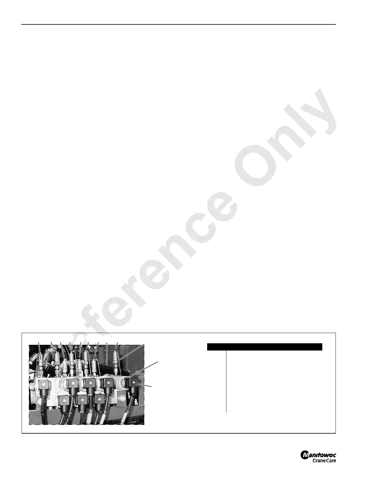
See Figure 2-12 for identification of the pressure senders.
FIGURE 2-12
Item Description
1 Left Track Forward/Reverse
2 Right Track Forward/Reverse
3 Swing Left
4 Swing Right
5 Boom Hoist Cylinder (Boom Up)
6 Boom Hoist Pump (Boom Up)
7 Front Load Drum (Hoist)
8 Rear Load Drum (Hoist)
9 Auxiliary Load Drum (Hoist) (optional)
Gauge Coupler
(typical)
P697
98765431
Electric Plug
(typical)
Pressure Sender
(typical)
Left Side of Pumps
2

 Loading...


