INTRODUCTION 777 SERVICE MANUAL
1-8 Published 10-01-2012, Control # 045-08
An accessory tandem gear pump supplies supercharged
filtered oil to the suction ports of some of these pumps,
provides oil to establish cylinder valve actuation, and
pressure oil to establish band brake release.
The PC controls each pump EDC in reaction to operator
commands through the system’s control handles. The PC
compares the handle commands with feedback information it
derives from continuous monitoring of the system’s sensors.
Data derived from this monitoring can be viewed on a digital
display screen in the operator’s cab by selecting the desired
information.
Hydraulic Pumps
See Figures 1-5 and 1-6 for following procedures.
Variable displacement, axial piston pumps are used in the
boom, front and rear hoists, swing, travel, and auxiliary hoist
(optional) systems. Each pump contains a cylinder block in
which the pistons are positioned axially around the drive
shaft, a tiltable swashplate against which the pistons ride, a
servo mechanism that tilts the swashplate, and two
multifunction valve cartridges.
Pump displacement is dependent upon the speed at which
the engine drives the pump through the pump drive gearbox
and the angle at which the swashplate is tilted. The engine
provides the horsepower available for work, while the
swashplate tilt provides speed control. An electrical hand
throttle sets engine speed; temporary increases are
accomplished with an electrical foot throttle.
The pump’s external EDC sets the amount and direction that
the swashplate is tilted by internal servo control cylinder.
Tipping direction establishes the direction that the oil flows
from the pump to the system actuator. This determines the
direction of motor rotation or cylinder movement.
A gerotor type gear pump is internally mounted on the end of
each system pump’s drive shaft. Charge pump (2) draws oil
directly from the hydraulic tank’s suction manifold or filtered
make-up oil. The charge pump delivers it to the closed-loop
at approximately 350 psi (24 bar) depending upon load and
engine speed and the setting of charge pump relief valve (3).
The charge oil provides oil cooling, positive pressure
maintenance in the low-pressure side of the loop, control
pressure for the pump swashplate servo mechanism, and
make-up oil for replacement due to internal leakage. From
the charge pump, the oil flows to charge flow make-up check
valves (4) in the multifunction cartridge, and passes over the
check valve on the low side of the loop. It combines with oil
returning from the system actuator and enters the system
pump.
In the system pump, the oil pressure holds each piston in
turn against the face of the swashplate as the engine rotates
the cylinder block.
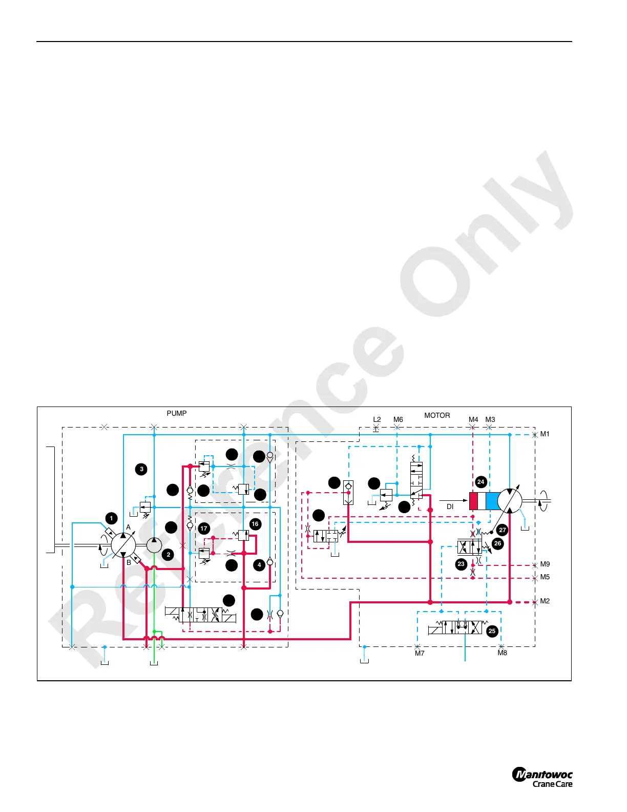
FIGURE 1-5
M1002
(23 bar)
340 PSI
T2
T3
A
MAX.
P
U
M
P
D
R
I
V
E
B
B
A
A
DC
EGFD
OUTPUT
INPUT
PUMP
MOTOR
B
A
M8
M7
M3M4M6
L2
M9
M2
M5
M1
25
1
3
24
23
27
26
16
17
2
4
DISP.
T1
21
20
19
16
4
21
17
18
18
28
22
30
29

 Loading...


