Manitowoc Published 10-01-2012, Control # 045-08 1-9
777 SERVICE MANUAL INTRODUCTION
1
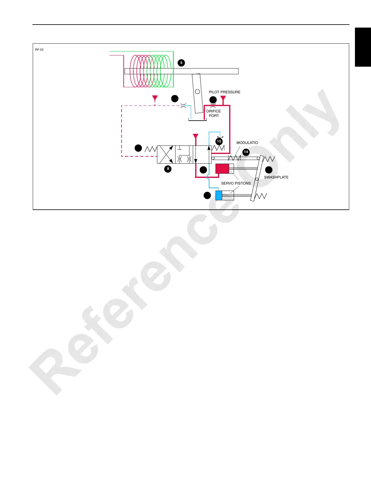
The PC transmits a command signal to one of the two coils in
the EDC via two of the four EDC connector pins. The first pin
energizes the coil. The current travels through the coil and
returns to the connector as negative charge through the
second pin. The polarity changes for opposite stroke
direction and positive current returns to the coil through the
second pin and back to negative through the first pin. This
charge cycle causes armature (Figure 1-6) to become more
magnetized, initiating its movement to begin blocking orifice.
The increasing blockage of orifice causes a larger pressure
increase in right port than in left port, resulting in a pressure
imbalance across spool. This pressure imbalance
overcomes the resistance of spring and initiates the
movement of spool causing internal servo control cylinder to
pressurize and servo oil to be routed to tank. This movement
causes swashplate to shift, and initiate the flow of oil out of
the pump. As swashplate shifts, spring chamber is pulled
opposite the direction of spool with linkage. This actuation
centers and maintains spool in a neutral position until the 16
psi (1.1 bar) preset pressure of spring is reached.
Because the swashplate is now tilted, the pistons are
reciprocated within the cylinder block as the block rotates.
The lengthening stroke of each piston draws returning oil into
the cylinder; as the stroke shortens, the oil is pumped out of
the pump cylinder to the motor cylinders at system pressure.
Note that when the swashplate is not tilted, there is no output
from the pump.
The amount that the swashplate is tilted determines the
amount of oil that is pumped to the motor or cylinder.
Increasing the swashplate tilt increases the stroke length,
causing more oil to be pumped to the system motor or
cylinders.
At this point, pressure develops within the closed-loop
system while the resistance of the load on the system
actuator is overcome. When movement begins, the volume
displacement of the pump maintains the actuator speed.
More flow from the pump operates the actuated system
faster to perform the desired activity.
Since each system pump operates in a bi-directional closed-
loop circuit, the pumps contain two different multifunction
valve cartridges, each of which consists of system relief
valve (16, Figure 1-5), make-up check valves (4), and
pressure limiting valve (17) which protect the crane’s
hydraulic system from excessive pressure and heat buildup.
When the preset system pressure is reached in the loop, the
multifunction valves limit system pressure by causing the
pump to destroke and/or allowing oil to transfer from the high
pressure side of the loop to the low pressure side.
In the travel pump’s main hydraulic loop, the system relief
make-up check valve, and pressure limiting sections of the
multifunction valve will respond when the preset relief
pressure at port B is reached. At this time, the oil pressure
actuates the spring in pressure limiting valve (17), shifting its
spool to open an exhaust path for the oil. Since servo check
valves (18) are spring loaded with an opening pressure of
750 psi (52 bar), the oil flows through the exhaust port of
displacement control valve (19). The exhaust port of
displacement control valve is restricted by orifices (A),
causing flow to pressurize servo control cylinder (1) and
destrokes the pump’s swashplate to limit the system
FIGURE 1-6
SWASHPLATE
SERVO PISTONS
PILOT PRESSURE
ORIFICE
RF-02
PORT
MODULATION
ORIFICE
PORT
SPRING
CONTROL VOLTAGE
ARMATURE
SPOOL
PILOT PRESSURE
PILOT PRESSURE
SPOOL
SPRING
FROM CONTROLLER
7
11
9
6
10 12
13
14
8
5

 Loading...


