Manitowoc Published 10-01-2012, Control # 045-08 7-7
777 SERVICE MANUAL POWER TRAIN
7
1. If the specified engine speeds cannot be obtained during
the adjustment steps, the engine speed sensor (on
engine flywheel housing) may not be adjusted properly:
a. Turn sensor out several turns.
b. Turn sensor in until it lightly bottoms out against a
flywheel gear tooth.
c. Turn sensor out 1/2 turn.
d. Securely tighten jam nut to lock sensor adjustment.
2. In cab, move hand and foot throttles to low idle.
3. Stop engine.
4. Open cover on junction box.
5. Remove jumper wire between terminals #14 and #15, if
there is one.
6. Set potentiometers to following positions:
a. Gain potentiometer to mid-position (50). This setting
should prevent the engine from surging.
b. Droop potentiometer fully counterclockwise (0).
c. Smoke potentiometer fully counterclockwise (0).
7. Set flexible coupling damping switch to ON position.
8. Set RMT SPD switch to 4-8V position.
9. Set A/B switches to RUN 1 position — A switch OFF and
B switch ON. This is the controlled low idle setting.
10. Start engine (hand throttle fully forward and foot throttle
fully raised to low idle).
11. Scroll to engine speed on digital display screen. See
digital display to monitor engine speed during remaining
adjustment steps.
12. Using ENGINE RPM buttons in junction box, press INC
(increase) or DEC (decrease) button to set engine
speed as close to 1,000 rpm without going over.
13. Stop engine.
14. Set A/B switches to RUN 2 position — A switch ON and
B switch OFF.
15. Start engine and run it at full throttle (hand throttle fully
back or foot pedal fully down).
16. Press INC or DEC button to set engine speed as close to
2,100 rpm as possible without going under.
17. Stop engine.
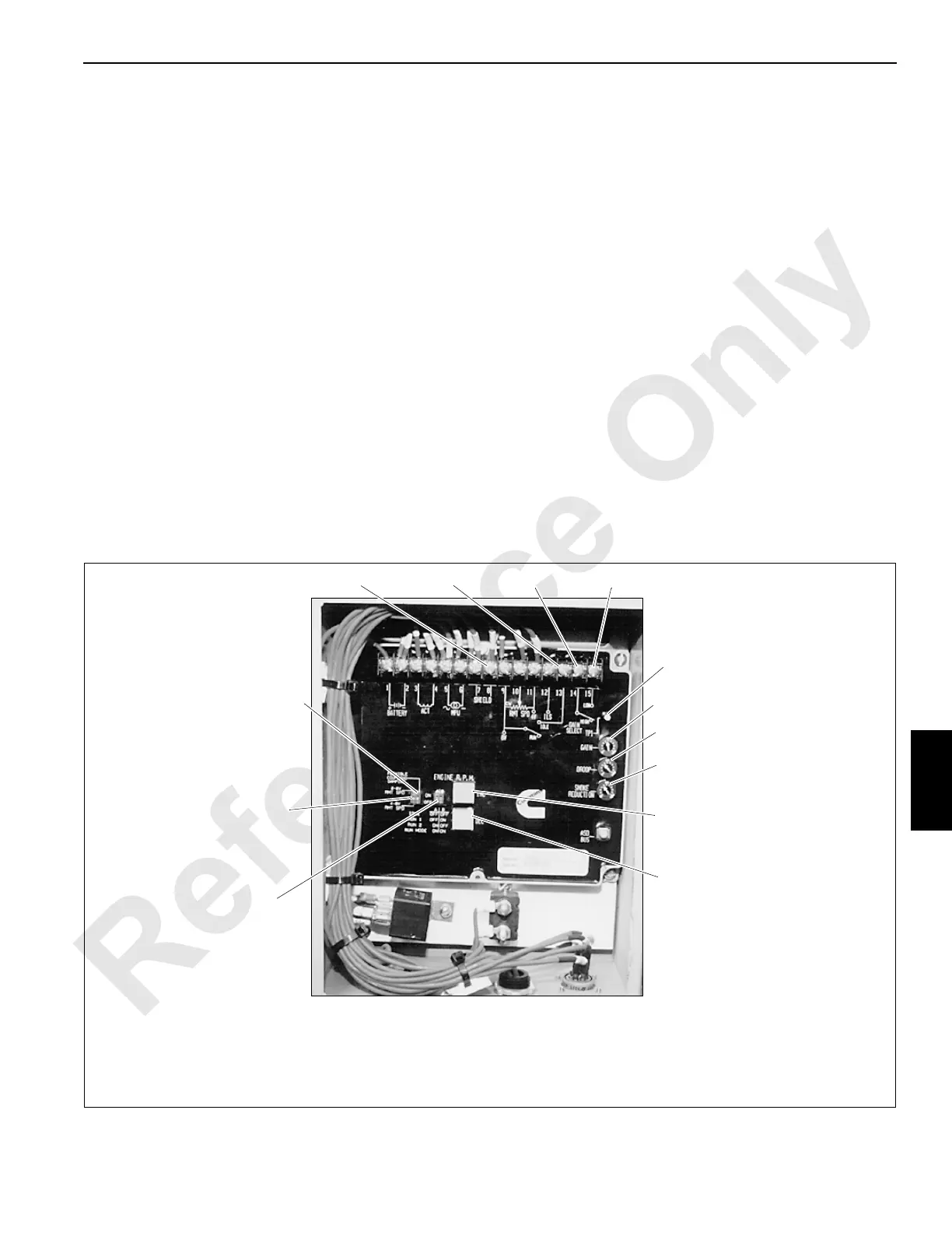
FIGURE 7-5
Terminal 9
Terminal 13
Terminal 14 Terminal 15
Flexible Coupling
Damping Switch
RMT SPD
Switch
A/B
Switches
Junction Box on
Front of Engine
P131
Terminal
TP-1
Gain Potentiometer
Droop Potentiometer
Smoke Reduction
Potentiometer
INC Button
DEC Button

 Loading...


