INTRODUCTION 777 SERVICE MANUAL
1-24 Published 10-01-2012, Control # 045-08
NOTE: If a control handle is moved when the operator is
out of seat, the FUNCTION IS PARKED fault
message is displayed.
• RATED CAPACITY INDICATOR/LIMITER This function
depending upon installation, may or may not
automatically stop a lifting function if load picked is
beyond the limits of the crane’s capacity. See operator’s
manual of crane being used for description of function.
• LEFT/RIGHT COUNTERWEIGHT LIMITS automatically
stops lifting the counterweights when installing them
onto the crane. The crane also automatically stops when
booming down with the hold down pendants installed.
The operating limit alerts activates when one of the limit
switches is opened. The digital display identifies the
operating limit by displaying it on scroll display and actuates
an intermittent blinking yellow light and beeper in the cab
when any operating limit listed in Digital Display Readings in
Section 10 of this manual, can be reached. The limit is
shown in the operating limit section of the digital display if
display scroll switch is used to scroll the display up or down
to the operating limits display function. After the cause for the
limit is corrected, the alert turns off.
Limit bypass switch allows the crane functions to be
operated beyond the limits for maintenance purposes only.
For example, excess wire rope can be spooled onto the load
drum or removed from the load drums after an operating limit
has been activated with use of the limit bypass switch.
When depressing the limit bypass switch and scroll up switch
at the same time, diagnostic information is displayed on the
display screen in addition to the normal operating screens.
The diagnostic information provided gives the status of many
of the crane components, and PC inputs and outputs during
normal operation.
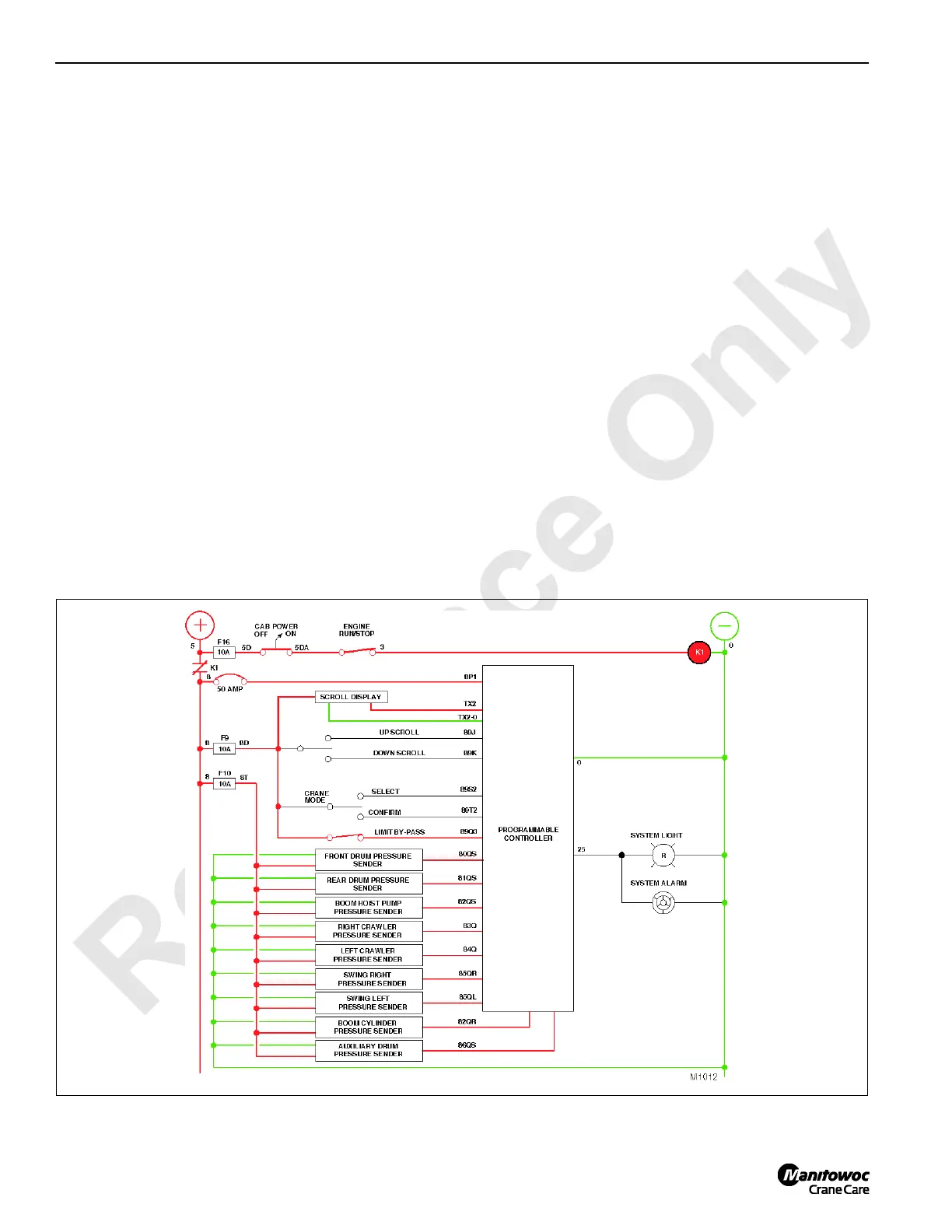
Pressure Monitoring Senders
See Figure 1-15 for following procedures.
When Kl is energized and contact Kl is closed, voltage is
available to the crane hydraulic pressure monitoring
senders. In addition to providing hydraulic system pressure
information for the scroll display, the PC also uses this
information to control the operation of the crane, such as
pressure memory to hold and control the load, and
observation of the track system ensuring both crawlers
rotate in unison for straightness in direction of travel.
During normal operation of the hydraulic pressure sender,
system voltage or 12 volts nominal is available to the
pressure senders when Kl relay energizes. The voltage
supply passes through the voltage regulator and is reduced
to a regulated 8 volts before entering the instrumentation
amplifier and strain gauge/resistor bridge.
At 0 psi (this situation can only occur when the engine is off
and power is on) approximately 8 volts regulated enters the
strain gage and resistor bridge. At this time resistance values
measured across the resistors and strain gauges are of
FIGURE 1-15

 Loading...


