Manitowoc Published 10-01-2012, Control # 045-08 3-13
777 SERVICE MANUAL ELECTRIC SYSTEM
3
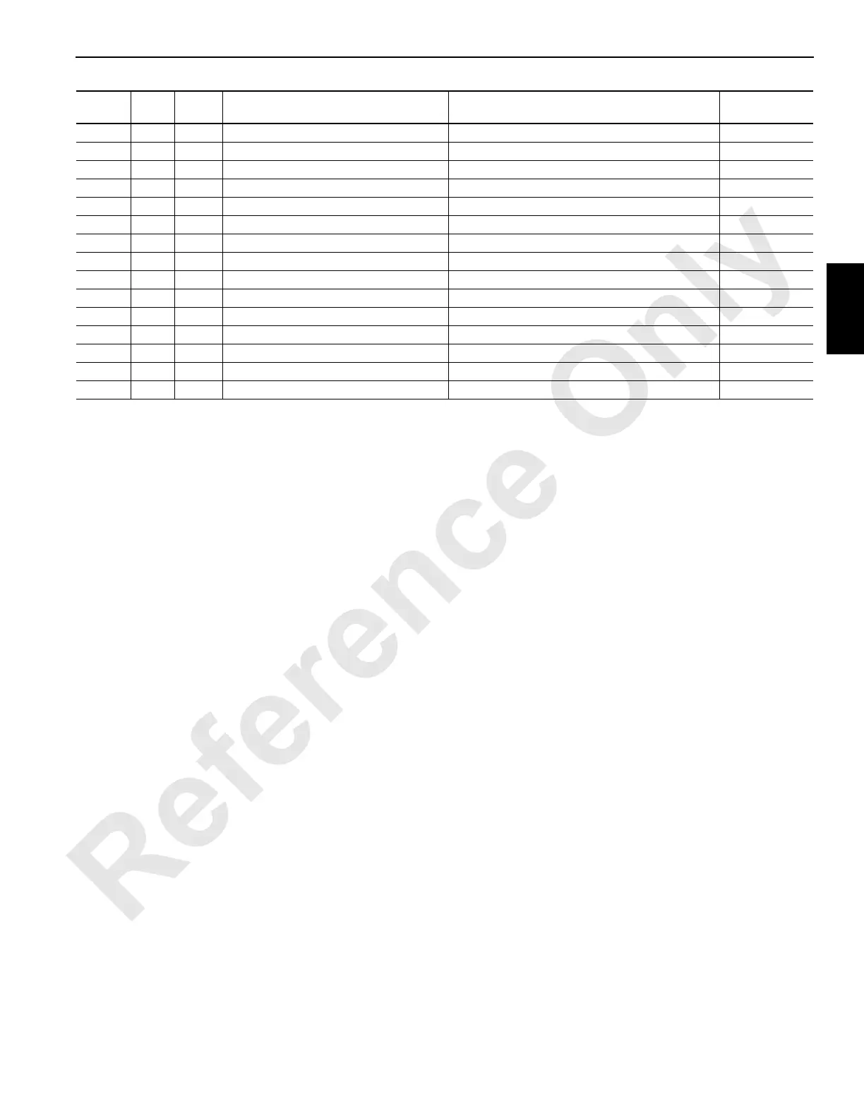
89Z3 D-09 DI-38 Rear Drum Disc Brake Park Switch 12 VDC Nominal (when brake is applied) I/O 3 J10-16
89Z4 E-24 DI-56 Hydraulic Filter Alarm 6 12 VDC Nominal (when filter is bypassing) I/O 4 J12-20
89ZA B-04 DI-4 Left Side Counterweight Limit 12 VDC Nominal I/O 1 J6-10
89ZB B-05 DI-5 Right Side Counterweight Limit 12 VDC Nominal I/O 1 J6-11
89ZD B-20 DI-20 Left Front Drum Clutch Switch 12 VDC Nominal I/O 2 J8-12
89ZE B-22 DI-22 Right Front Drum Clutch Switch 12 VDC Nominal I/O 2 J8-14
89ZF B-27 DI-27 Set-up Remote Boom Up 12 VDC Nominal I/O 2 J8-19
89ZG B-28 DI-28 Set-up Remote Boom Down 12 VDC Nominal I/O 2 J8-20
89ZH B-31 DI-31 Left Rear Drum Clutch Switch 12 VDC Nominal I/O 3 J10-09
89ZJ B-36 DI-36 Right Rear Drum Clutch Switch 12 VDC Nominal I/O 3 J10-14
89ZK E-18 DI-50 Boom Cylinder Hold 12 VDC Nominal I/O 4 J12-14
89ZL A-15 AI-12 Load Indicator Select Mode 12 VDC Nominal I/O 2 J7-56
89ZN A-18 AI-15 Load Indicator Display Scroll Up 12 VDC Nominal I/O 2 J7-62
89ZP A-19 AI-16 Load Indicator Display Scroll Down 12 VDC Nominal I/O 2 J7-64
89ZZ B-11 DI-11 Maximum Boom/Luffing Angle Limit Bypass 12 VDC Nominal I/O 1 J6-17
Wire # Pin # I/O # Description
Test Voltage
(DC unless otherwise specified)
Connection
 Loading...


