Manitowoc Published 10-01-2012, Control # 045-08 5-5
777 SERVICE MANUAL HOISTS
5
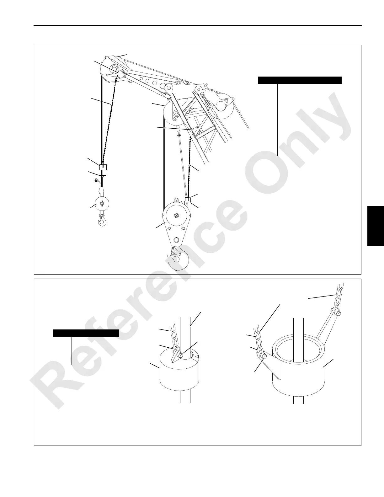
FIGURE 5-3
A1007
#78 Boom Shown;
#78T Boom and
Luffing Jib Similar
Item Description
1 Weight Ball
2 Lift Block
3 Weight
4 Chain - 8 ft (2.4 m)
5 Limit Switch Assembly
6 Upper Boom Point
7 Lower Boom Point
8 Chain - 8 ft (2.4 m)
9 Lift Plate
10 Load Block
1
3
2
3
4
5
6
5
8
9
10
7
FIGURE 5-4
A1007
Lower Boom Point (multiple part),
Lower Boom Point (two lines over point),
Universal Anchor Joint, or
Luffing Jib Point (multiple part)
Fixed Jib Point,
Upper Boom Point,
Luffing Jib Point (single part), or
Lower Boom Point (single part)
Item Description
1Chain
2 Shackle
3 Weight
4 Connecting Pin
1
2
3
4
1
2
3
4
See Load Block Reeving drawing
for Suggested Location of Weight
Two Chains Prevent
Weight from Turning
Dead-End Load Line
or Slowest Live Line

 Loading...


