Manitowoc Published 10-01-2012, Control # 045-08 5-15
777 SERVICE MANUAL HOISTS
5
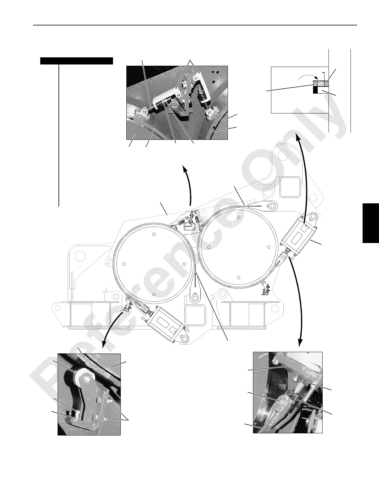
FIGURE 5-12
A1015
View A
View B
READJUST Brake When Leading Edge
of Spring Sleeve Reaches This Line
SAFE WORKING RANGE
DRUM BRAKE ADJUSTMENT INDICATOR
See Operator’s Manual for Procedure
Typical Each Brake
Rear
Load
Drum
Front
Load
Drum
View D
Right Side Shown
Left Side Similar
View C
P534
P535
P533
Item Description
1Eyebolt
2Spring Guide
3 Drum Flange
4 Brake Lining
5 Adjusting nut
6Lock Nut
7 Leading Edge of
Spring Sleeve
8 Starting Point
9 Readjust Point
10 Guard
11 Dead End
12 Brake Actuator
13 Connecting Pin
14 Jam Nut
15 Actuator Connector
16 Brake Band
17 Nuts and Bolts
18 Set Screw
19 Roller Guide
1
2
4
3
5
6
7
8
9
10
11
12
13
16
14
15
17
18
6
3
4
3
4
11
12
19

 Loading...


