TROUBLESHOOTING 777 SERVICE MANUAL
10-30 Published 10-01-2012, Control # 045-08
Test 2 (Continued)
To determine if the correct voltage is available from the hand
and foot throttle, use a digital multimeter to test at the EFC
box. With engine off and power on, verify 5.88 volts DC at
TB1-J, 3.84 volts DC at TB1-L, and.005 volts DC at TB1-G.
While in low idle, verify 5.87 volts DC at TB1-J, 3.81 volts DC
at TB1-L, and.007 volts DC at TB1-G. Use the engine as the
ground contact when testing at these terminals.
To determine if the correct voltage is available from the
engine RPM transducer, use a digital multimeter to test at the
EFC box. While in low idle, verify 6.58 volts AC is present
between TB1-C and TB1-D. If this reading is not obtained,
the engine RPM transducer may require servicing. See
Tes t 5.
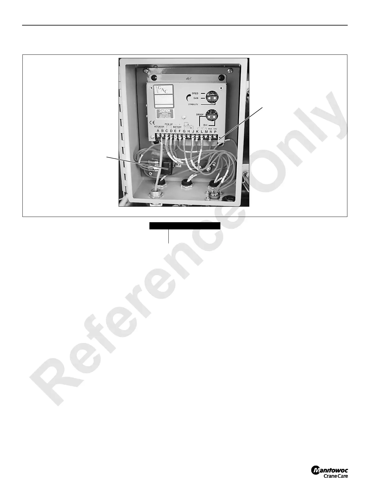
Item Description
1 Terminal block TB1
2EFC relay
TB1 Test Points – for Cummins C260 Engine
TB1-F Battery (+) TB1-B Actuator (4EFC) TB1-J Remote speed pot (68J)
TB1-E Battery (-) TB1-C Magnetic pick up (24) TB1-L Remote speed pot (68K)
TB1-A Actuator (3EFC) TB1-D Magnetic pick up (0) TB1-G Remote speed pot (68L)
2
1
P855
FIGURE 10-4

 Loading...


