Manitowoc Published 10-01-2012, Control # 045-08 1-17
777 SERVICE MANUAL INTRODUCTION
1
The programmable controller uses the binary mathematical
system for its basic alphabet.
The binary system is based on 2 rather than 10 as is our
mathematical system. This is because the controller
recognizes only 0 and 1 as OFF and ON voltages. As 0 and 1
are two numbers, the system is called binary, meaning
composed of two alternate units or bits (the digits 0 and 1).
The basic letters of this system or counts are exponents of
the number 2. These are formed into words or bytes of eight
(or sixteen) numbers each. These numbers must be 1, 2, 4,
8, 16, 32, 64, and 128 (for an 8-bit controller), or a
combination thereof up to 255.
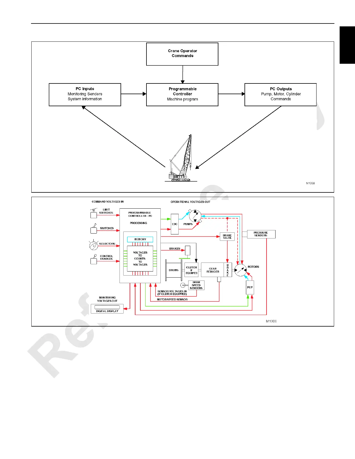
They are used to represent the electrical inputs to the
controller. The controller processes this information by
comparing it to its programming requirements, and its stored
data or memory, and then provides appropriate voltages to
the electric control devices of the crane’s components.
The monitoring sensors include limit switches; engine
operation, hydraulic oil, and boom angle senders; pressure
senders in each closed-loop hydraulic circuit; and boom,
load drum, and auxiliary hoist (optional) motor speed
senders.
Pressure senders measure system pressures and supply the
PC with equivalent voltages. The pressures are memorized
FIGURE 1-10
FIGURE 1-11

 Loading...


