Home
Manitowoc
Construction Equipment
777
Manitowoc 777 Service And Maintenance Manual
4
of 1
of 1 rating
306 pages
Give review
Manual
Specs
To Next Page
To Next Page
To Previous Page
To Previous Page
Loading...
Reference
Only
INTRODUCTION
777 SERVICE MANUAL
1-30
Published 10-01-2012, Control #
045-08
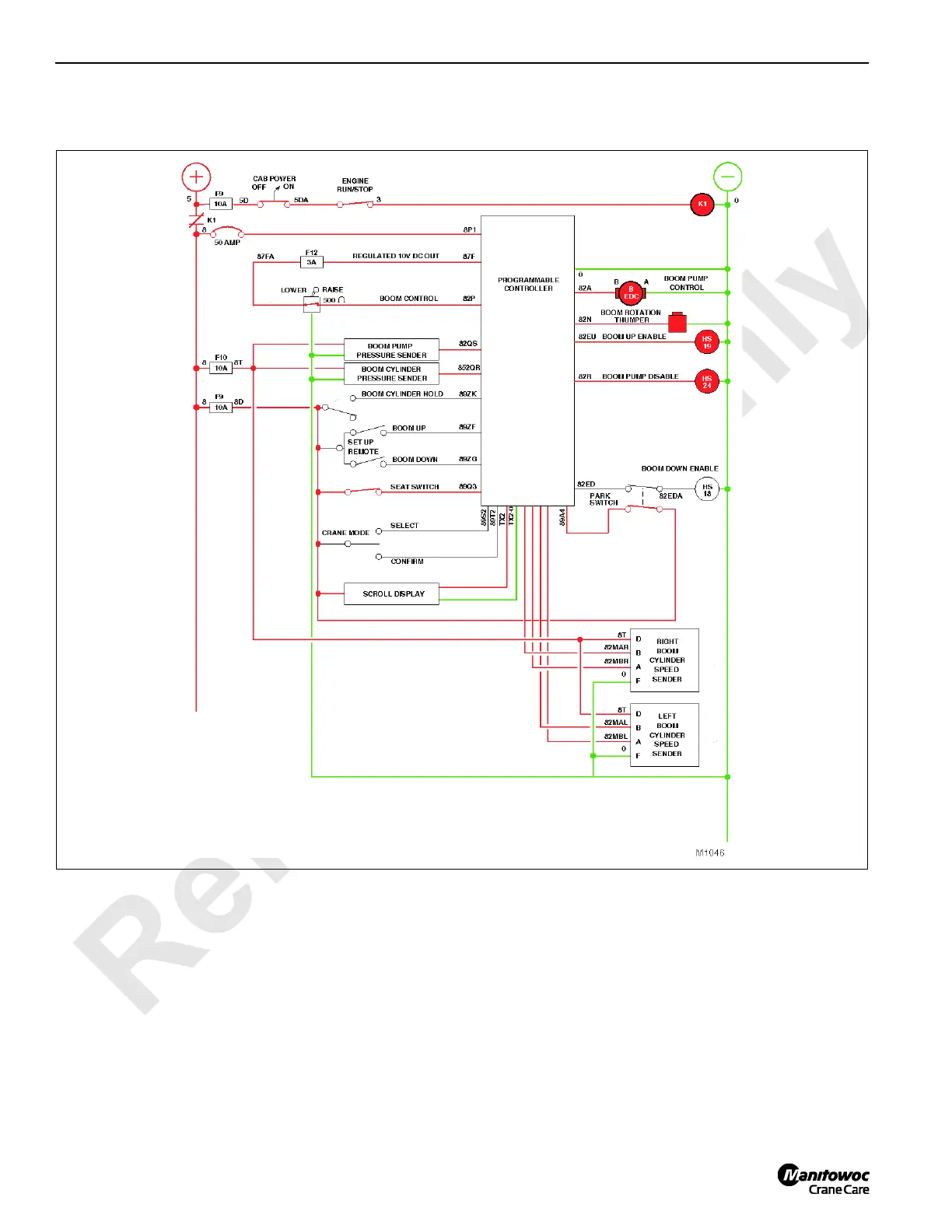
PC are b
locked
by the ne
utral
switch o
n the co
ntrol ha
ndle
.
Unless the Boom Cylinder Hol
d switch is on, the boom pump
does no
t stroke an
d the boo
m load h
olding val
ves maint
ain
the position of the
boom cylinders.
FIGURE
1-
18
41
43
Table of Contents
Table of Contents
5
Safe Maintenance Practices
13
Maintenance Instructions
13
Identification and Location of Components
15
Crane Orientation
15
General Operation
19
Operating System
19
Hydraulic Components
19
Hydraulic Pumps
20
Hydraulic Motors
22
Charge Pressure
23
Main System Pressure
23
Accessory System Pressure
23
Hydraulic Supply
23
Hydraulic Tank
24
Filtration
24
Suction Manifold
27
EPIC Programmable Controller (PC)
28
Supercharge Manifold
28
Oil Return Manifolds and Cooling System
28
Standard Crane Mode
30
Other Crane Modes
30
Digital Display
31
Voltage Availability
32
Brake Release System
38
Hydraulically Released
38
Load Drum Clutch Release System (with Free Fall)
39
Boom System
41
Boom Hoist Rotation Indicator
41
Counterweight Handling
41
Boom off
41
Boom Raise
43
Boom Lower
45
Swing System
48
Swing Lock
48
Off
49
Swing
49
Travel System
51
Off
51
Left Crawler Forward
51
Travel Detent Button
52
Load Drum Pawl
53
Drum Pawl Engage
54
Drum Pawl Disengage
54
Load Drum (Full Power Mode)
55
Liftcrane Operation
56
Off
56
Hoist
56
Lower
58
Clamshell Operation: Clamshell Mode
59
Programming
59
Off
59
Close Bucket
59
Hoist Bucket
61
Open Bucket
62
Lower Bucket
63
Load Drum (Free Fall Mode)
64
Front Drum in Free Fall
66
Crane Setup Systems
69
Carbody Jacking System
69
Jacking Cylinder Extend
69
Jacking Cylinder Neutral
69
Jacking Cylinder Retract
71
Crawler Attachment System
73
Crawler Lock Pin Extend
73
Crawler Lock Pin Retract
74
Optional Systems
75
Luffing Jib Hoist System
75
Auxiliary Hoist System
76
Auxiliary Hoist Rotation Indicator
77
Auxiliary Drum Pawl System
77
Auxiliary Hoist off
77
Auxiliary Hoist Raise
77
Auxiliary Hoist Lower
78
Abbreviations
80
Hydraulic Schematics
83
Hydraulic System - General
83
Checking and Replacing Hydraulic Hoses
83
Hydraulic System Maintenance
84
Safety
84
Storing and Handling Oil
84
Storing and Handling Parts
84
Inspecting System
84
Servicing Pumps
85
Cleaning Fill Cap Assembly
85
Replacing Filter Elements
86
Filter 1
86
Filter 2
87
Filters 3 and 4
87
Changing Oil
89
Tightening Hydraulic Connections
90
Pipe Thread Connection
90
SAE Straight Thread Connection
91
ORS Connection
92
Split Flange Connection
92
SAE Flare Connection
93
Programmable Controller Calibration Procedures
94
Controls Calibration
94
Pressure Sender Calibration
94
Pressure Sender Replacement
94
Load Drums, Swing, Track, and Boom Hoist Pump
95
Boom Hoist Cylinder
95
Disc Brake Operational Test
97
Operational Test
97
Shop Procedure
99
Initial Oil Fill
102
Pressure Sender Calibration
105
Initial Start-Up
106
Controls Calibration
108
Pressure Adjustments
108
Charge Pressure Checks
108
Accessory System Pressure Checks
109
Band Brake Relief Valve Pressure Check
110
Drum Clutch Pressure Adjustment
110
Operating Pressure Checks
111
Boom Hoist Leakage Test
111
Operating Speed Checks
112
Electrical Drawings and Schematics
115
Checking and Replacing Electrical Components
115
Abbreviations and Symbols
116
Test Voltages
117
Controller Board Layout
117
Pin Identification
118
Wire Identification
123
Description Identification
128
Display Readings
133
Operating Conditions
133
Operating Limits
133
System Faults
133
Selecting Display Language
135
Crane Diagnostics
138
Drum 1, 2, and 8
138
BHST (Boom Hoist)
138
Swing
138
Track
138
A1 (Handles)
139
D1 and D2 (Digital Outputs and Inputs)
139
Crane Software Installation
144
CPU and Eprom Compatibility
144
EPROM (Chip) Identification
144
Eprom Replacement
145
Counterweight Limit Switch Adjustment
146
Adjustment
146
Bench Setup
146
Engine Control Module Ground Modification
147
Installation
147
Test before Installing Counterweights
147
Dielectric Grease
148
Connector Pin Identification
149
Mini-Change Type Connectors
149
2-Pole Plugs
149
3-Pole Plugs
150
5-Pole Plugs
151
10-Pole Plugs
152
Micro-Change Type Connectors
153
Quick-Change Type Connectors
153
4-Pole Plugs
153
3-Pole Plugs
154
Section 4
157
Automatic Boom Stop Adjustment
157
Maximum Boom Angle
157
Operation
157
Maintenance
157
Bypass Limit Test
159
Adjustment
159
Physical Boom Stop
160
Operation
160
Removal
160
Boom Angle Indicator
162
Adjusting Angle Indicator
162
Sensor Replacement
162
Pendulum-Type 120° Potentiometer
162
Solid State Sensor
162
Servicing Boom Hoist Cylinder
164
Boom Hoist Cylinders - Welding
164
Before Welding on Crane
164
Boom and Jib Inspection and Lacing Replacement
165
Inspection Intervals
165
Inspection Guidelines
165
Replacement Criteria
165
Dents
166
Gradual and Sweeping Bends
166
Corrosion and Abrasion
166
Kinks
168
Cracks and Breaks
168
Chord Straightness
168
Ordering Lacings
170
Assistance
170
Boom or Jib Identification
170
Ordering Lacings from Lacing Drawings
171
Ordering Lacings Without Lacing Drawings
172
Repair Procedure
173
Extent of Repair
173
Preparing for Welding
173
Repair Facility
173
Outdoor Repairs
173
General Equipment Requirements
173
Repair Procedures and Processes
174
Lacing Replacement
174
End Lacing Replacement
175
End Lacing Replacement on an Insert (Angle and Tubular Chords)
176
End Lacing Replacement on Tapered Sections (Tubular Chords)
176
Lacing Removal - Boom Section with a Bent or Bowed Chord Member
177
Determining Amount of Stick Electrode Needed
177
Inspection Checklist
183
Record Keeping
183
Section 5
187
Hoist Drawings
189
Minimum Bail Limit Adjustment
189
Weekly Maintenance
189
Wire Rope Removal
189
Electric Wiring
189
Adjustment
191
Block-Up Limit Installation and Adjustment
192
Operation
192
Installation
192
Adjustment
192
Block-Up Limit Control Deactivated
192
Block-Up Limit Control Activated
192
Storing Electric Cable
194
Disconnecting Block-Up Limit Control
197
Removing Jib or Boom Point
197
Maintenance
197
Adjustment
198
Drum Brake Adjustment
200
Full-Power Operation (Free Fall Off)
200
Free Fall Operation (Optional)
200
Brake Inspection
200
Brake Adjustment
201
Foot Pedal Adjustment
202
Drum Pawl Adjustment
204
Actuator Removal
204
Actuator Installation and Adjustment
204
Drum Pressure Roller Adjustment
206
General
206
Adjustment
206
Wire Rope Lubrication
207
Wire Rope Inspection and Replacement
207
Keeping Records
207
Inspecting Wire Rope
207
Frequent Inspection
207
Periodic Inspection
207
Rope Not in Regular Use
207
Replacing Wire Rope
207
Distributing Wire Rope Wear
209
Sheave, Roller, and Drum Inspection
210
Load Block and Hook-And-Weight Ball
213
Maintenance and Inspection
213
Section 6
217
Manual Release of Swing Brake and Lock
219
Manual Release Procedure
219
Section 7
219
Battery Maintenance
223
Safety Information
223
Causes of Battery Failure
223
Overcharging
223
Undercharging
223
Lack of Water
223
Hold-Downs
223
Overloads
223
Multiple Battery System
224
Maintenance
224
Weekly - Check Electrolyte Level
224
Every 2 Months - Test Batteries
224
Charging
225
Storage
225
Battery Electrical Disconnect Switch
225
Quarterly
225
Engine Air Cleaner Maintenance
226
Mounting
226
Inspection
226
Service
226
Engine Clutch Adjustment
227
Operation
227
Adjustment
227
Engine Throttle Adjustment - Cummins C330
228
Foot Throttle Linkage Adjustment
228
Electronic Fuel Control Adjustment
228
Engine Throttle Adjustment - Cummins 6CTA8.3-C260 Engine
230
Foot Throttle Linkage Adjustment
230
Electronic Speed Control Adjustment
230
Setting High Speed
230
Setting Gain and Stability
230
Test Voltages
231
Engine Throttle Adjustment - Caterpillar 3176B and 3176C Engines
232
Foot Throttle Linkage Adjustment
232
Engine Speed Calibration
232
Engine Throttle Adjustment - Cummins QSL 340, QSC8.3, QSM11, or QSX15 Engine
233
Foot Throttle Linkage Adjustment
233
Engine Speed Calibration
233
Wiring Diagram
233
Onboard Diagnostics
234
Engine Stop Light
234
Engine off Diagnostics
234
Engine Warning Light
234
Engine Maintain Light
234
Turntable Bearing Bolt Torque
237
Bearing Installation
237
Torque Requirements
237
Bolt Replacement
237
Lubrication
237
Torque Values
237
Torque Sequence
237
Torque Intervals
237
Crawler Adjustment
238
Maintenance
238
Tread Slack Adjustment
239
Adjustment Guideline
239
Adjustment Procedure
239
Hydraulic Hand Pump
240
Assembly
240
Maintenance
240
Air Removal
241
Operation
241
Section 9
243
Lubrication
243
Section 10
247
Safety Summary
249
General Guidelines
249
Introduction
249
Test Equipment
250
Troubleshooting Charts
251
Testing
276
Test 1 - Battery Test (12 and 24 VDC)
276
Test 2 - Electric Fuel Control (EFC) Box Test Points
277
Test 3 - Checking Resistance at Engine Temperature Switch
279
Test 4 - Checking Resistance at Engine Oil Pressure Sender
280
Test 5 - Cleaning and Adjusting the Engine RPM Transducer (Past Production)
281
Test 6 - Testing for Voltage at the Fuse Box
282
Test 7 - Checking Voltage at the Control Handle
283
Test 8 - Adjusting the Control Handle Potentiometer
284
Test 9 - Location of Pump Test Ports
285
Test 10 - Location of Motor Test Ports
287
Test 11 - Manually Stroking the Pump
289
Test 12 - Setting the Pump Pressure
290
Test 13 - Setting Pump Neutral
291
Test 14 - Adjusting Pump Charge Pressure Relief
292
Test 15 - Checking Pump Charge Pressure
293
Test 16 - Checking Charge Pressure at Motor Port X1
294
Test 17 - Testing the Motor PCP and Pump EDC
295
Test 18 - Testing for Pump and Motor Leakage
296
Test 19 - Testing Hydraulic Solenoid Brake Valves
297
Test 20 - Checking Hydraulic Brake Pressure
298
Test 21 - Adjusting the Lower Accessory Relief Valve
299
Test 22 - Adjusting Jacking Counterbalance Valves
300
Other manuals for Manitowoc 777
Operator's Manual
222 pages
4
Based on 1 rating
Ask a question
Give review
Questions and Answers:
Need help?
Do you have a question about the Manitowoc 777 and is the answer not in the manual?
Ask a question
Manitowoc 777 Specifications
General
Brand
Manitowoc
Model
777
Category
Construction Equipment
Language
English
Related product manuals
Manitowoc 2250
312 pages
Manitowoc 14000
270 pages
Manitowoc 31000
126 pages
Manitowoc Grove RT890E
24 pages
Manitowoc Grove YB5520
144 pages
Manitowoc Grove YB5515
134 pages
Manitowoc 14000 2 Series
4 pages
Manitowoc GROVE GMK 6400
960 pages
Manitowoc 16000 Series 2
2 pages
Manitowoc GROVE GMK5150L
1040 pages
Manitowoc 14000 1 Series
6 pages
Manitowoc Grove GMK 5250L
958 pages