USE MANUAL
MINISENTRY-2
107911_D User manual MINISENTRY-2_En.docx
MIRION TECHNOLOGIES (Canberra) S.A.S, BP249, ZI de Vauzelles, 3760
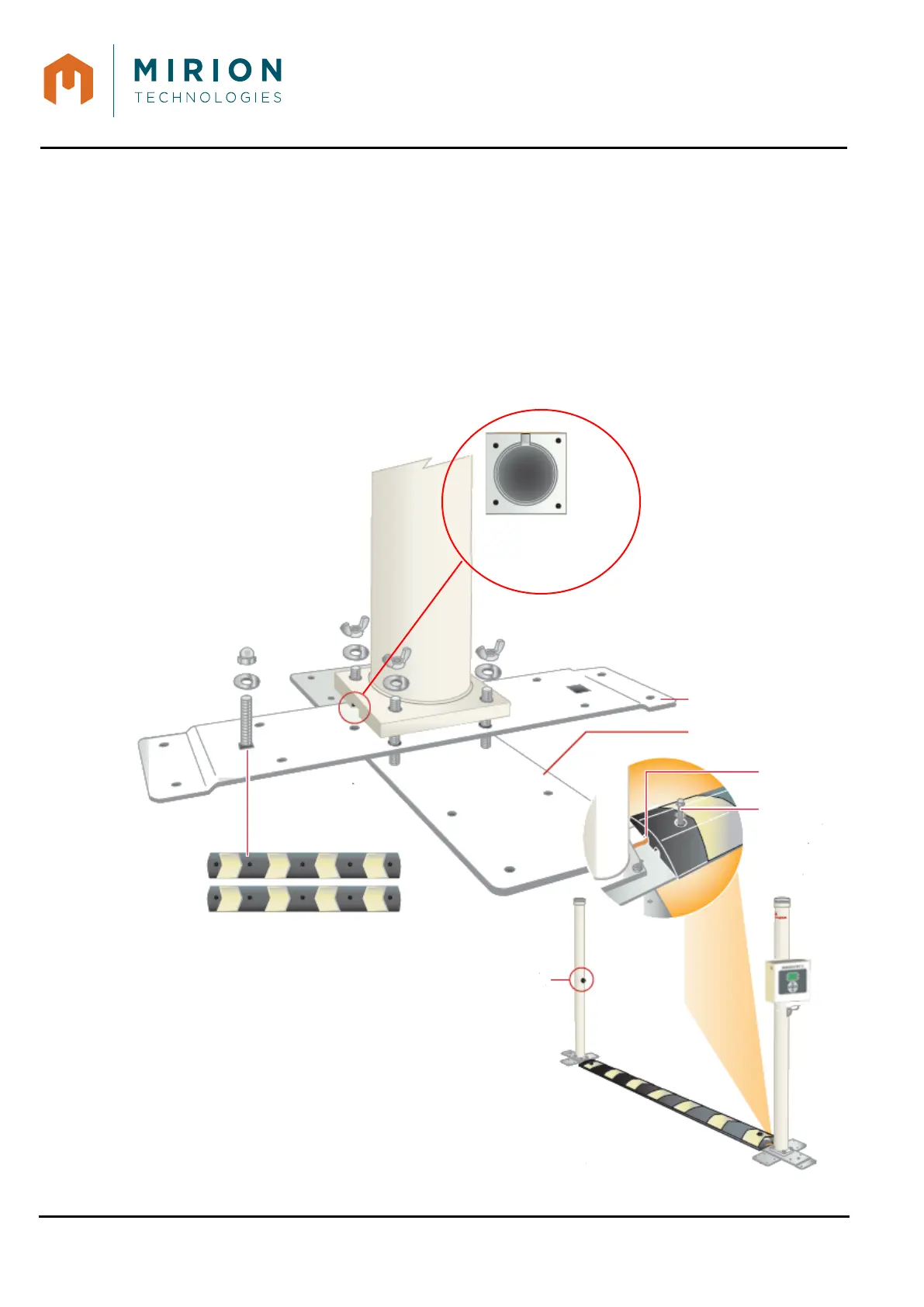
4. Remove (and keep) the flat washers and wing nuts from the footplates.
5. Align the “A” pedestrian baseplate’s bolts with the holes on the “B” vehicle baseplate as shown.
6. Lower the base of the detector post over the screws as shown.
Note: The footplate bolts and post holes are spaced so the footplate can only be attached in
one direction on the post.
7. Place a flat washer and a wing nut on each of the footplate’s retaining bolts. Tighten each of the
four wing nuts.
8. Use the bolt to secure the rubber spacer as shown. Repeat steps 5–8 for the other leg.
9. Run the connection wires under the rubber spacers and set the desired distance between the
detector posts.
attached here - facing the
wire notch on the detector
Channel for wire
protection
rubber spacer
to the footplate
with the bolt
Rubber spacers must be secured with
stakes (not included) or by other means
so they do not slip and shear cables.
are placed offset to
ensure one correct
position.
detector posts
must face one