EasyManuals Logo

Mitsubishi 700 Series User Manual

Mitsubishi 700 Series
280 pages
To Next Page IconTo Next Page
To Previous Page IconTo Previous Page
Page #158 background imageLoading...
Page #158 background image
PROTOCOL-SPECIFIC INFORMATION
145
9
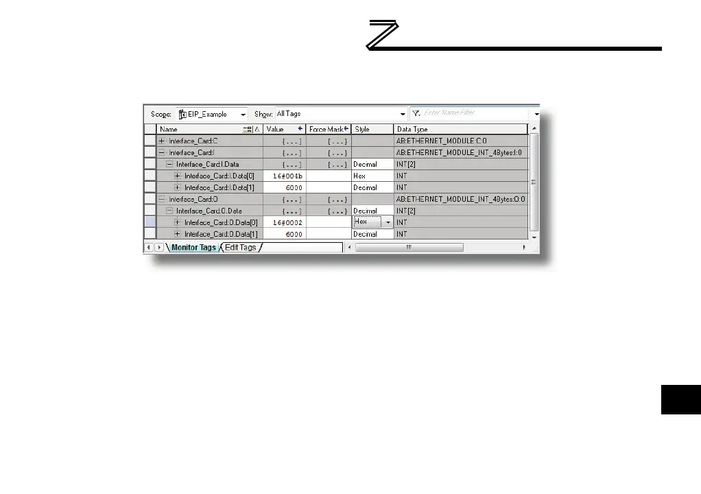
inverter’s command register. A value of 0x0002, therefore, means that the run forward bit has been
turned ON.
Figure 45: Controller Tags for I/O Access
Similarly, we can see that the second 16-bit word of output data (Interface_Card:O.Data[1]) has
been set to a decimal value of 6000. The default consumed data word configuration word offset 1
references register 2, which is the inverter’s frequency command register. A value of 6000,
therefore, equates to a frequency command of 60.00Hz.
The input data from the inverter shows similar expected results. Values of 0x004B and 6000
corresponding to registers 100 (status register) and 101 (output frequency), respectively, are
consistent with the inverter running at the parameter values commanded by the output tag.

Table of Contents

Questions and Answers:

Question and Answer IconNeed help?

Do you have a question about the Mitsubishi 700 Series and is the answer not in the manual?

Mitsubishi 700 Series Specifications

General IconGeneral
Control MethodVector Control
Overload Capacity150% of rated current for 60 seconds
Protection FunctionsOvercurrent, Overvoltage, Undervoltage, Overheat, Short circuit
Communication OptionsRS-485, Profibus, Ethernet
Output Power Range0.4 kW to 630 kW
Cooling MethodForced air cooling (fan) (Varies by model)
Operating Temperature-10 to +50°C (Varies by model, may be derated at higher temperatures)
Storage Temperature-20 to +65°C
Humidity95% RH or less (non-condensing)
AltitudeUp to 1000 m above sea level (Derating may be required above 1000 m)
Enclosure RatingIP20
ModelFR-A700, FR-F700, FR-E700, FR-D700, FR-S700

Related product manuals