


M
Melissa BakerAug 29, 2025
How to fix offset value equal to or larger than gain value on Mitsubishi MELSEC Q?
- MMark KennedyAug 30, 2025
Reset the Mitsubishi Controller so that the offset value is smaller than the gain value.

 Loading...
How to fix offset value equal to or larger than gain value on Mitsubishi MELSEC Q?
Reset the Mitsubishi Controller so that the offset value is smaller than the gain value.
How to solve scaling lower limit value equal to or greater than the scaling upper limit value on Mitsubishi Controller?
Set CH scaling upper/lower limit value so that the scaling upper limit value is greater than the scaling lower limit value.
How to correct warning output lower limit value equal to or greater than the warning output upper limit value on Mitsubishi MELSEC Q Controller?
Make setting so that the warning output upper limit value is greater than the warning output lower limit value.
What to do if the fuse broken detection occurs in Mitsubishi MELSEC Q?
If the fuse for the coincidence signal external output section has blown in your Mitsubishi Controller, it must be replaced by a qualified technician from the Service Center. Contact your branch office or distributor with a detailed description of the issue.
What should I do if the value set to the intelligent function switch 5 is other than 0 in Mitsubishi MELSEC Q?
Re-set the correct parameter value in the parameter setting of GX Developer.
How do I resolve the issue of a specified digital value being outside the range on my Mitsubishi MELSEC Q Controller?
Set a value that is within the range.
How do I fix setting outside the output range on Mitsubishi Controller?
Reset to the correct parameter with GX Developer parameter setting.
What to do if more than one channel was set at the same time during offset/gain settings on Mitsubishi MELSEC Q Controller?
Set the correct value in offset/ gain setting mode (Un\G22, Un\G23).
What should I do if the value set to the G(P).OGLOAD instruction, G(P).OGSTOR instruction or save data classification setting is outside the range on Mitsubishi MELSEC Q Controller?
Set the value within the range.
What to do if the G(P).OGSTOR instruction was executed consecutively on Mitsubishi Controller?
Execute the G(P).OGSTOR instruction only once for one module. At the time of offset/gain setting, write a set value only once at one time.
| Series | MELSEC Q Series |
|---|---|
| Type | Modular PLC |
| Programming Software | GX Works2, GX Works3 |
| Category | Programmable Logic Controller (PLC) |
| I/O Modules | Digital I/O, Analog I/O, High-Speed Counter, Positioning |
| Communication | Ethernet, CC-Link |
| Programming Languages | Ladder Logic, Structured Text, Function Block Diagram, Sequential Function Chart, Instruction List |
| Memory | Flash Memory |
| I/O Points | Up to 4096 points (expandable with additional modules) |
| Power Supply | AC or DC power supply options available, depending on the base unit and modules. |
| Mounting | DIN rail mounting |
| Operating Temperature | 0°C to 55°C |
| Storage Temperature | -25°C to 75°C |
| Humidity | 5% to 95% (non-condensing) |
| Vibration Resistance | 10 to 57 Hz, 0.075mm amplitude |
| Weight | Varies depending on the module, from a few grams to several kilograms. |
| Shock Resistance | 147 m/s² (3 times each in X, Y, Z directions) |
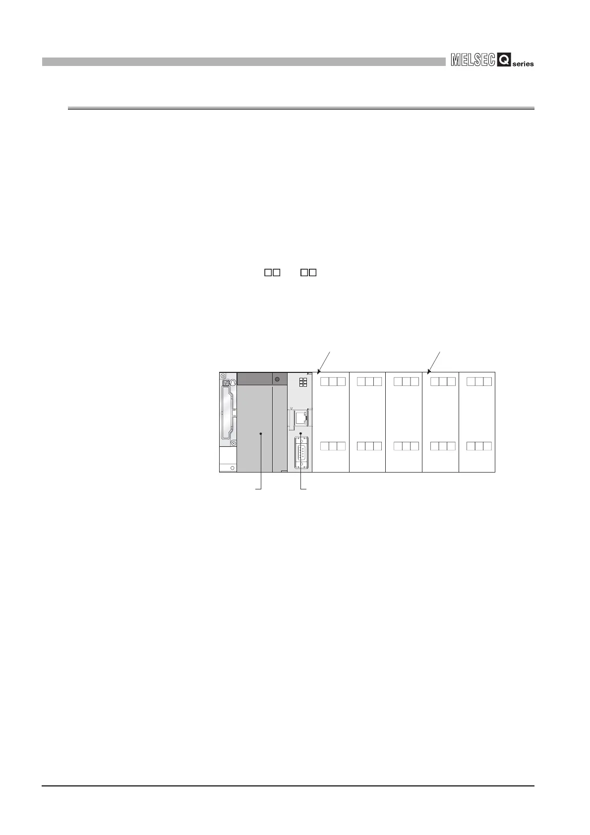
Describes the features of the C Controller module, including VxWorks, standard ROM, large data storage, and I/O control capabilities.
Explains device configuration, development environment connection, and system configuration overview for C Controller systems.
Details the base units, extension cables, power supply modules, and other components used with the C Controller module.
Provides the general specifications of the C Controller module, including operating ambient temperature, humidity, vibration, and shock resistance.
Lists the functions of the C Controller module, such as I/O module access, remote operation, and self-diagnostic functions.
Explains critical handling precautions for the C Controller module, including environment, installation, and connection safety.
Explains how base units and slots relate to I/O number assignment for the C Controller module.
Explains user memories (Standard ROM, Work RAM, Battery-backed-up RAM, CompactFlash) and system memory.
Details the product requirements for the development environment, including personal computer specifications and operating system.
Explains common operations for utilities, including starting, exiting, setting connection targets, and displaying help screens.
Outlines bus interface functions and MELSEC data link functions supplied with SW PVC-CCPU for accessing modules and CPUs.
Defines the multiple CPU system concept, explaining how multiple CPU modules work together for enhanced performance.
Explains system configuration for multiple CPU systems, including device compatibility and connection methods.
Details the mounting positions of CPU modules (C Controller, Basic QCPU, High Performance QCPU, Motion CPU) in a multiple CPU system.
Explains data communication methods using MELSEC data link functions between CPU modules, including auto refresh and shared memory.
Lists parameters required for multiple CPU system operation, highlighting setup necessity and consistency checks in the C Controller setting utility.
Provides specific precautions for using AnS series modules, including applicable I/O and special function modules and control CPU settings.
Provides fundamental steps for troubleshooting, including visual checks, fault verification, and narrowing down the error cause.


