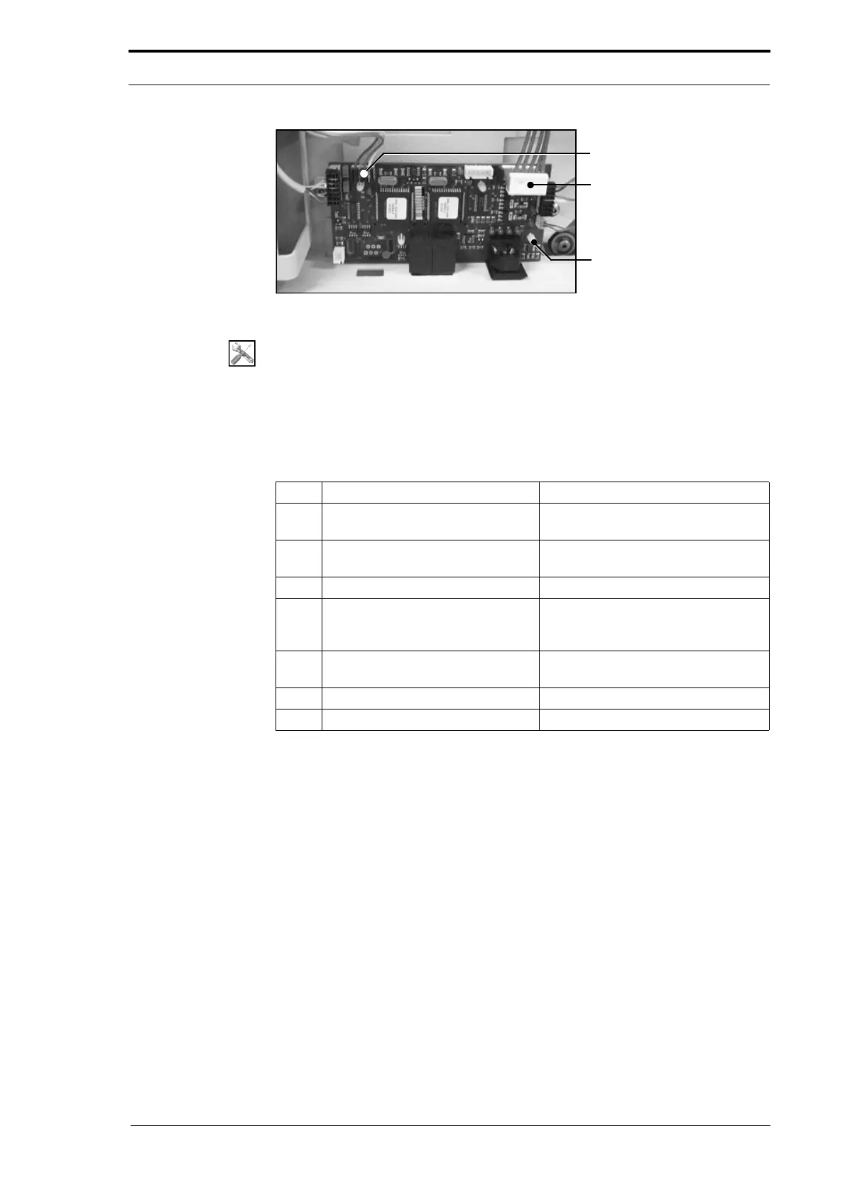
Data Bus Cable
PCB Support Post
Power Bus Cable
4. Service Procedures - Replace Components - Gathering Area
172 Morgana DocuMaster MFC - Service Manual
Figure 4.185 The Base Control PCB
Tools:
• Allen Key: 3mm
Before you start:
• Remove the bottom RH side cover (See Section 4.2.5)
• Disconnect the online booklet maker interface cable (See the MFC User Operating
Instructions Manual).
Step Action Information
1 Disconnect the Data bus cable
from PL1.
(See Figure 4.185)
2 Disconnect the Power bus cable
from PL2.
(See Figure 4.185)
3 Disconnect all other cables.
4 Remove the bin control PCB. Push in the locking tab on each PCB
support post
and pull gently on the
PCB to release it.
5 Fit the replacement base control
PCB and
connect all of the cables.
6 Check the CPU configuration. (See Section 4.5.24).
7 Initialise the bins. (See Section 4.5.6).