Morgana DocuMaster MFC - Service Manual 173
4. Service Procedures - Replace Components - Electrical Cabinet
4.12 Replace Components - Electrical Cabinet
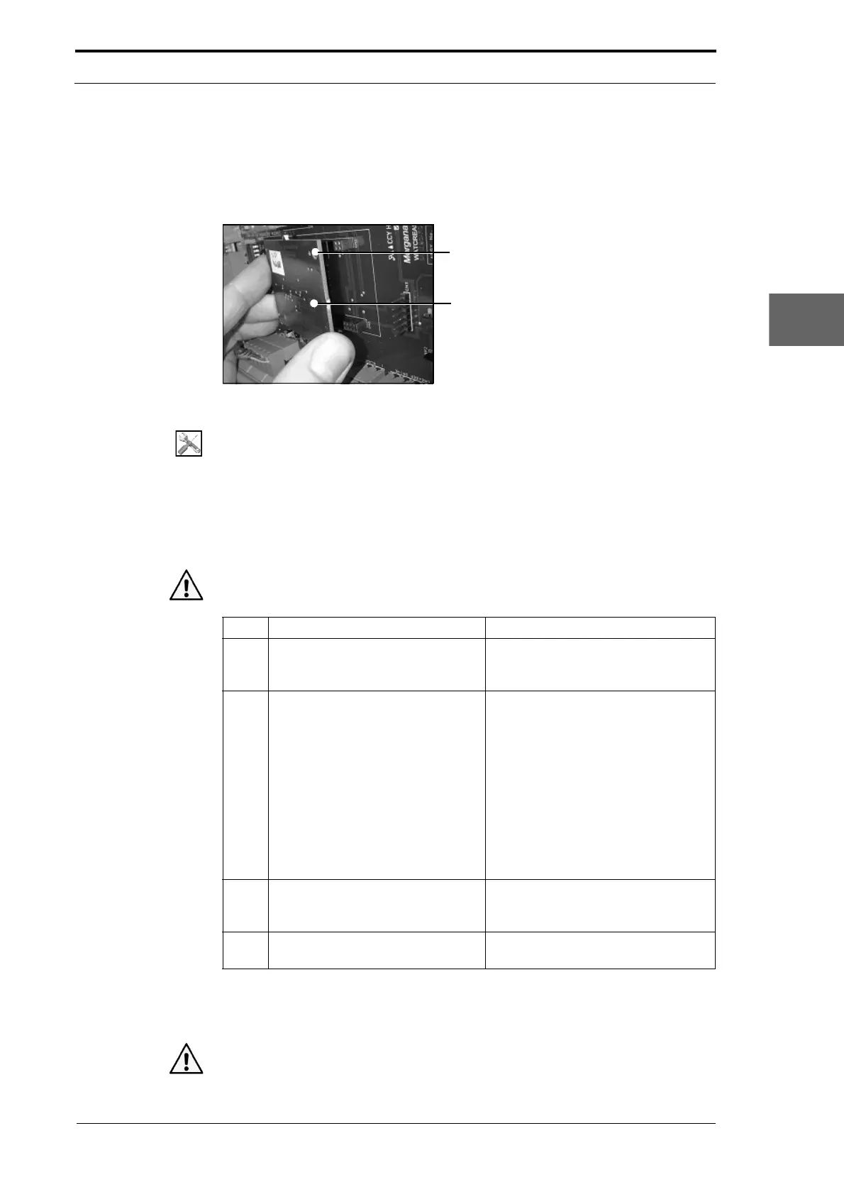
4.12.1 Replace the Processor PCB
Hole must be at the top RH corner
Processor PCB
Figure 4.186 Replace the Processor PCB
Tools:
• Anti-static wrist-band and lead.
Before you start:
• Set the main input switch to OFF (0).
• Disconnect the main power cord from the MFC.
• Remove the electrical cabinet over (See Section 4.2.12).
Warning: Use extreme caution not to touch live circuits when the MFC is turned on.
Step Action Information
1 Connect the anti-static wrist band
and lead
to the earth post below
the 5V/24 PSU.
2 Remove the processor PCB.
• Hold both sides of the processor
PCB.
• Pull the processor PCB away
from the control PCB a small
mount at the LH side.
• Pull the processor PCB away
from the control PCB a small
amount at RH side.
• Repeat these steps until the PCB
is disengaged from the sockets
on the control PCB.
3 Install the replacement processor
PCB
.
The processor PCB must be installed
so that the hole is in the top RH
corner (see Figure 4.186).
4 Update the creaser control
sof
tware if required.
(See Section 7.8).
4.12.2 Replace the Controller PCB Assembly
Caution: Before you replace the controller PCB assembly make sure that you record