Morgana DocuMaster MFC - Service Manual 89
4. Service Procedures - Machine Adjustments and Calibration
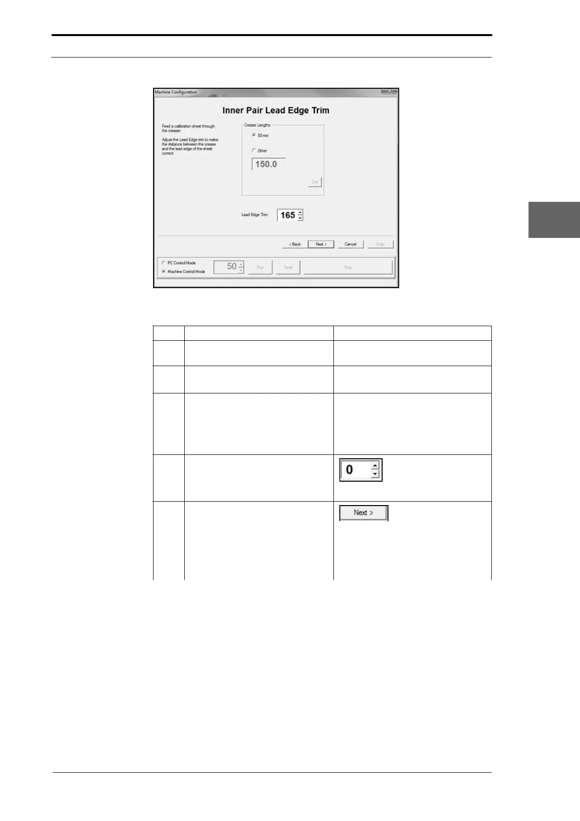
Figure 4.67 The Inner Sensor Pair Lead-Edge Adjustment Page
Step Action Information
1 Do a stretch crease check (if you
did not do it before
this).
(See Section 4.5.18.2).
2 Feed a single sheet of test stock
through the MFC.
• Remove the sheet from the
gathering area.
3 Do a check to see if the lead-edge
tr
im is correct.
• Put the sheet on a flat surface.
• Do a check to see if the distance
between the crease and the
lead-edge of the sheet is 50mm
(see Figure 4.66).
4 Adjust the inner pair lead-edge trim
to
make the distance between the
crease and the lead-edge of the
sheet measure 50mm.
Set a lead-edge trim
value in the setting
box
5 Repeat Steps 2 thru 4 until the
lead-ed
ge trim measurement is
correct.
Left Click NEXT> when
done.
Note: The Machine Config
uration
wizard will show the next calibration
page and write the trim values to the
EEROM.