MultiSmart Installation & Operation Manual
7.4.3 Serial Ports
There are two RS232 (DB-9 - male) serial ports on the CPU Board. Either of these ports can be assigned to
a communications channel. All I/O lines are implemented.
The MultiSmart serial ports use the standard RS232 pin outs as tabled below. When connecting to say a
laptop, a cross over cable is required – as a minimum RX, TX and GND are required.
Pin Name Abbrev Direction
1 Carrier Detect CD Input
2 Receive Data RX Input
3 Transmit Data TX Output
4 Data Terminal Ready DTR Output
5 System Ground GND -
6 Data Set Ready DSR Input
7 Request to Send RTS Output
8 Clear to Send CTS Input
9 Ring Indicator RI Input
Table 2 – Serial Port Pin Outs
7.4.4 SD Memory Card
The SD memory card socket takes standard SD memory cards. The SD card can be used in a number of
ways:
• As extra storage space for data logging.
• To install new firmware.
• Can be used to load or save configuration files from/to the MultiSmart unit.
7.4.5 USB
The USB port takes standard USB memory sticks. USB can be used in the same manner as for SD cards.
7.5 DSP Board
The Digital Signal Processor board handles the I/O, communicates between multiple I/O modules and is
where the main power supply is connected.
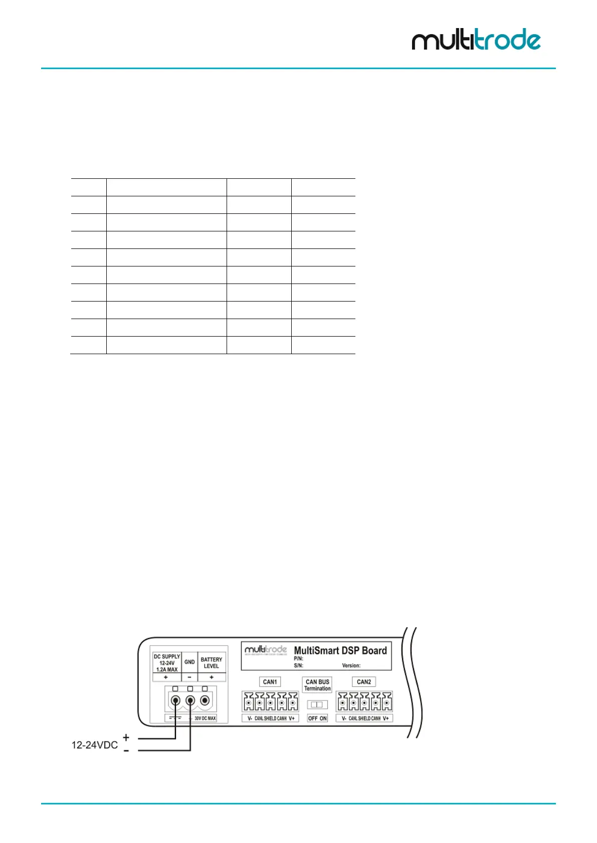
7.5.1 Power Supply Connector
The 12-24VDC power supply is connected into the DSP board as shown below:
Figure 49 – Connecting the power supply
MultiSmart_IO_Manual_R20 Page 49 of 260