MultiSmart Installation & Operation Manual
NOTE: When a MultiTrode conductive probe is used, the sensitivity settings above for DINs are not used.
Instead the overall setting for the probe is independently used. See Section 14.8.7 for more detail.
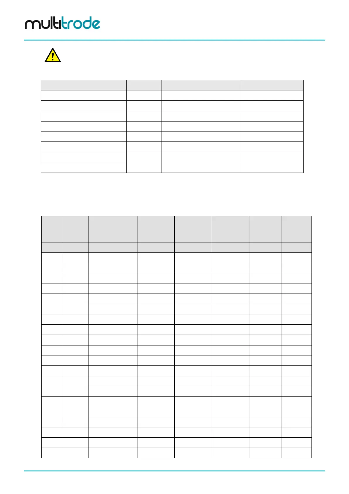
Digital Input configuration - for reference only:
Type of Input Mode Typical Sensitivity or Range Invert?
Conductive Probe AC
20,000Ω
No
Seal Sensor (conductive) AC
40,000Ω
No
Flygt CLS CLS
Seal >4kΩ, Thermal <1kΩ
No
PTC Thermistor DC
3,000Ω
Yes
Flygt FLS DC
Seal >4kΩ, Thermal <545Ω
No
Normal Volt Free Contact Closure Digital 4Hz No (default) / Yes (N/C)
Failsafe Probe Sensor Fail Safe
4,000Ω
No
High Speed Counter High Speed 1kHz No (default) / Yes
Table 9 – Digital Input Mode Examples
14.4.2 Digital Input Summary Table
This table summarizes the capabilities of the digital inputs on the Pump Station Manager (3PC) board:
DIN#
Volt
Free
Input
PTC Thermistor,
Seal Sensor,
Flygt FLS
Conductive
Probe
Low Speed
Counter
(4Hz)
High Speed
Counter
(1kHz)
Flygt CLS
Fail Safe
Probe
Mode Digital DC AC Digital High Speed CLS FailSafe
1
2
3
4
5
6
7
8
9
10
11
12
13
14
15
16
17
18
19
20
Table 10 – Digital Input Capabilities
Page 102 of 260 MultiSmart_IO_Manual_R20