MultiSmart Installation & Operation Manual
7.3.5 Analog Output
The pump control I/O board has one analog output (non-isolated) which produces a 4-20mA output signal.
This output can be used to transmit the water level (or reflect the value in any AIN on the MultiSmart unit) or
to control a Variable Frequency/Speed Drive, i.e. VFD. (VFD functionality is an optional feature which needs
to be ordered if required. It can be enabled after purchase).
• Maximum Load (Impedance) – 800 ohms
• Resolution 0.2%
• Non-isolated
Figure 47 – Analog Output
7.4 CPU Board
The CPU Board is the core of the MultiSmart pump station manager and provides serial and Ethernet
communications ports, controls the user interface and has SD card and USB interfaces.
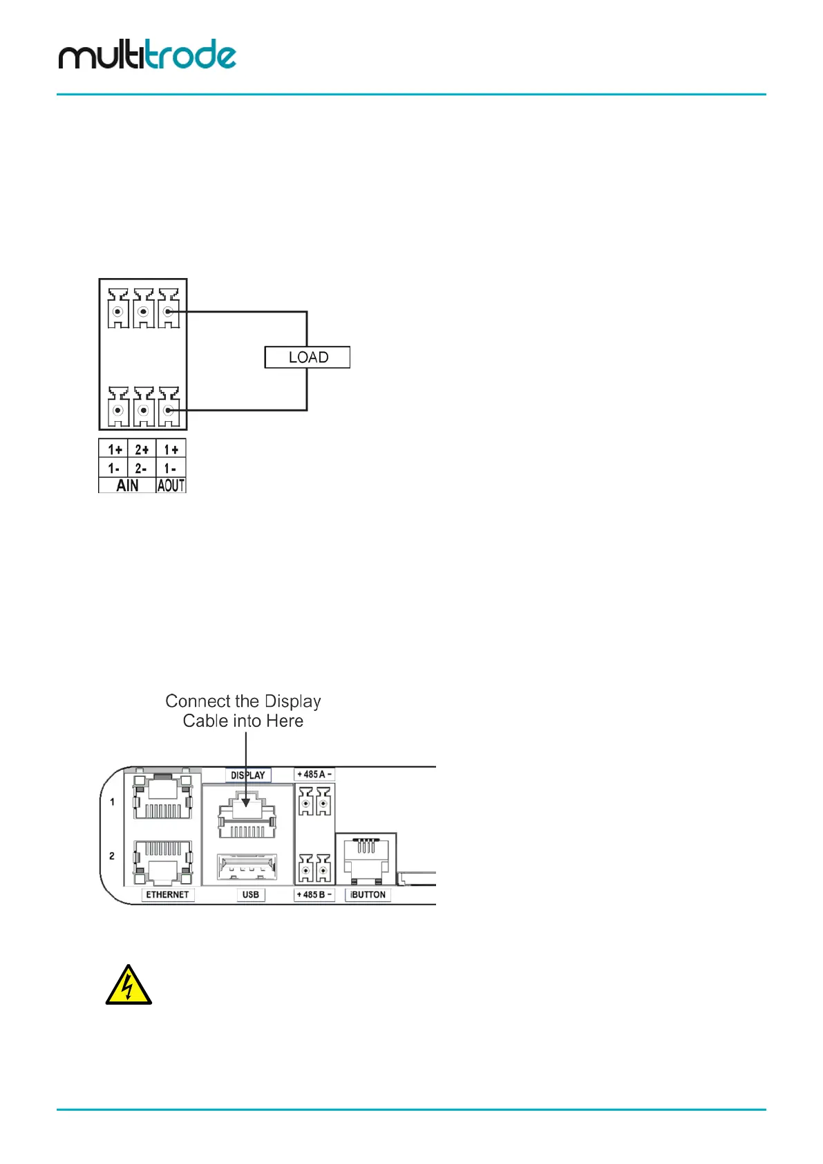
7.4.1 Connecting the User Interface Display
Connect the display into the RJ45 socket on the MultiSmart unit CPU Board as shown below.
Figure 48 – Connecting the display cable
WARNING: DO NOT CONNECT THE DISPLAY INTO THE ETHERNET PORT
7.4.2 Ethernet Port
The CPU Board has two 10Mbit/s, RJ45, Ethernet ports for SCADA communications using one of the
following protocols: Modbus or DNP3 over TCP/IP.
Page 48 of 260 MultiSmart_IO_Manual_R20