MultiSmart Installation & Operation Manual
NOTE: In order to make some changes, a reboot of the pump station manager may be necessary – a
message will be displayed. It is recommended that all pumps are turned off prior to rebooting.
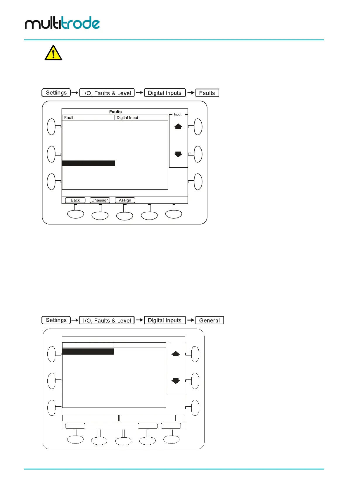
14.3 Unassigning Fault Inputs
Pump 1 CLS
Pump 1 FLS TopBoard DIN 12
Pump 1 Seal Fault
Pump 1 Thermal Overload TopBoard DIN 14
Pump 1 Motor Overtemp
Pump 1 CB Off/Trip TopBoard DIN 13
TopBoard DIN 15
Pump 1 Critical Fault
Pump 1 Delay Fail
Pump 1 Non-Critical Fault
Pump 1 Contactor Auxiliary
Figure 106 – Fault Screen
• Use the scroll buttons to highlight the Fault to be unassigned.
• Press the Unassign button, (Cancel and Save buttons will appear).
• Press Back and repeat for each fault needs to be unassign.
• Press Save at the end of the process.
14.4 Configuring Digital Inputs
Navigate to the Digital Inputs screen and press the General button.
General I/O Configuration
Input
Top Board DIN 01 DIN 01
Top Board DIN 06 DIN 06
Top Board DIN 08 DIN 08
Top Board DIN 02 DIN 02
Top Board DIN 03 DIN 03
Top Board DIN 04 DIN 04
Top Board DIN 05 DIN 05
Top Board DIN 07 DIN 07
Top Board DIN 09 DIN 09
Input Description
DIN 01
Description
abc
TopBoard DIN 01
Input
Cancel
Save
Back
Figure 107 – Digital Input Configuration Screen
Page 100 of 260 MultiSmart_IO_Manual_R20