MultiSmart Installation & Operation Manual
Pump 1 CLS
Pump 1 FLS TopBoard DIN 12
Pump 1 Seal Fault
Pump 1 Thermal Overload TopBoard DIN 14
Pump 1 Motor Overtemp
Pump 1 CB Off/Trip TopBoard DIN 13
Pump 1 Contactor Auxiliary TopBoard DIN 15
Pump 1 Critical Fault
Pump 1 Delay Fail
Pump 1 Non-Critical Fault
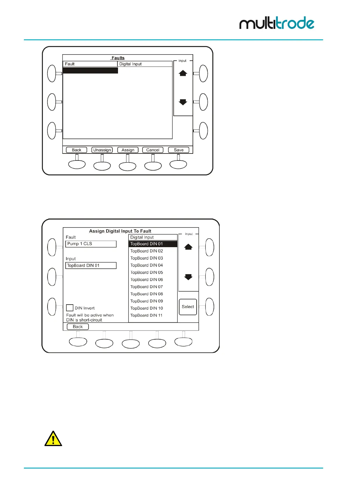
Figure 104 – Select a Fault
• Use the scroll buttons to highlight the type of fault input required
• Press the Assign button
Figure 105 - Assign the Selected Fault to a Digital Input
• Use the scroll buttons to highlight a Digital Input.
• Press the Select button to assign this input to the selected fault.
• Select DIN Invert if the fault needs to be active when the input is Low (open circuit), else the fault
will be active when the DIN is High (closed circuit).
• Press Back and repeat for each fault that needs to be assigned.
• Press Save at the end of the process.
NOTE: The Pump Holdout fault is hidden by default, so the “Fault” button does not flash when this fault
is active. Instead, the text “Holdout” appears in the pump status section.
MultiSmart_IO_Manual_R20 Page 99 of 260