MultiSmart Installation & Operation Manual
14.11 Configuring Digital Outputs
Digital outputs can be sourced from a wide variety of events occurring in the MultiSmart. They can be used
to activate external alarms, control pumps, reverse pumps, send signals to SCADA systems and connect to
other external logic (PLCs, relays, etc).
NOTE: Some digital outputs will already be in use as part of the initial configuration. D01 to D03 may
already be configured to control pumps and DO4 will be configured as an alarm output. All outputs can
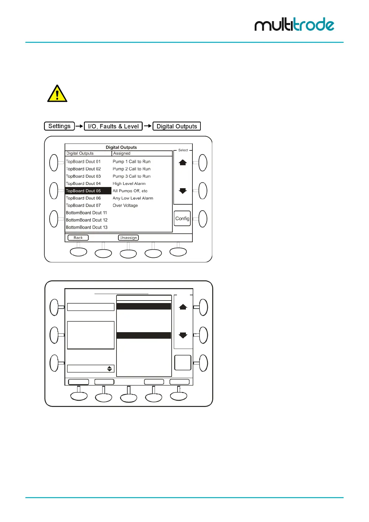
Digital outputs are configured from the I/O, Faults & Level screen.
Figure 126 – Digital Outputs Screen
All Pumps Available
Any Pumps Unavailable
Pump 1 Off or Unavailable
Pump 2 Off or Unavailable
All Pumps Unavailable
Any Pumps Faulted
Pump 1 Off
Pump 3 Off
Pump 3 Off or Unavailable
Any Pumps Off
All Pumps Off
Pump 2 Off
Configure Digital Outputs
Input
Back
Output
Inputs
Select
SaveAdvanced
Sources
TopBoard Dout 05
All Pumps Available
Cancel
Pump 2 Off
Operator
OR
Figure 127 – Configure Digital Outputs Screen
Multiple sources can be selected for a digital output. The operations, AND, OR & XOR can be performed on
the multiple sources before the digital output is set. Choose the first source, press Select and then select the
second source; the operator selection box then appears.
MultiSmart_IO_Manual_R20 Page 131 of 260