MultiSmart Installation & Operation Manual
9 Quick Commissioning Guide
MultiSmart is fully configurable from the LCD user interface. However, there is also a PC-based configurator
program with sophisticated functionality now available.
The MultiSmart is pre-programmed with a number of standard configurations for typical water/wastewater
applications. These include:
• Pump station manager with local level
• Pump station manager with remote level (reservoir)
• Reservoir monitor communicating with remote pump station
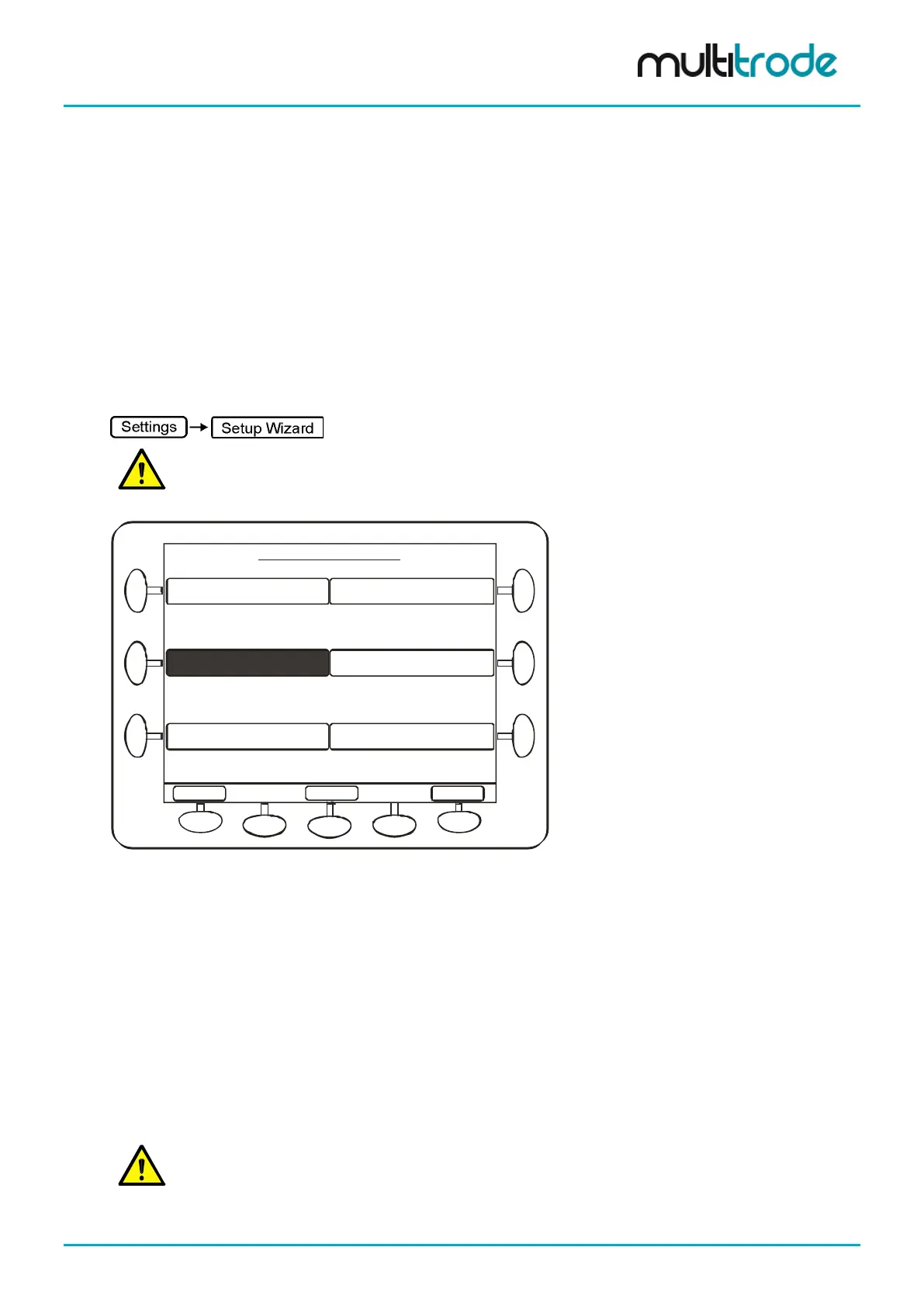
The Setup Wizard in the Settings menu takes you through a number of questions to configure the product.
NOTE: If the unit has already been setup by a previous user, then security may be enabled via a DIN
or by a PIN number. Refer to Section 11 for more detail.
Station Settings - Page 1 of 3:
Main
Advanced
More ...
Set Points
Setup Wizard
Alternation & Grouping
I/O, Faults, & Level
Station Optimization
Commission / Decom
Level and alarm setpoints, enable/disable
alarms, delays, maintenance mode & level
simulation
Commission a station - Fill/Empty Mode,
number of pumps, wells, level device
Alternation, fixed sequence and multiple
groups of pumps
Link faults to inputs, configure faults,
primary and backup level source, configure
AOUTs & DOUTs
Odor reduction, well-clean-out, blocked
pump detection, max run time, max station
starts, max pumps to run, profiles etc.
Take pumps in and out of service
Figure 70 – Settings Screen
When a pump station manager is selected, this also establishes one of the standard I/O connection diagrams
(see Section 7.2 to Section 7.2.4). The MultiSmart pump station manager establishes 1 of 4 standard
connection diagrams, depending on whether the configuration is:
• 2 pumps with a MultiTrode Probe / Duo probe
• 3 pumps with a MultiTrode Probe / Duo probe
• 2 pumps with a 4-20mA level device
• 3 pumps with a 4-20mA level device
These connections diagrams have a complete set of pump faults wired in (contactor auxiliary input, C/B off
trip, pump seal and thermal (or Flygt FLS), thermal overload).
NOTE: Disabling any faults not required is a very simple task – see Section 9.3 at the end of the Quick
Commissioning Guide.
MultiSmart_IO_Manual_R20 Page 63 of 260