MultiSmart Installation & Operation Manual
14.10 Configuring Analog Outputs
The MultiSmart Pump Control I/O Board (3PC) has one analog output available. The optional Motor
Protection Board (3MP) has three analog outputs available.
These analog outputs can be used for tasks such as re-transmitting an analog input or producing an analog
output value that matches the level in a well measured by a non-analog sensor, such as a probe.
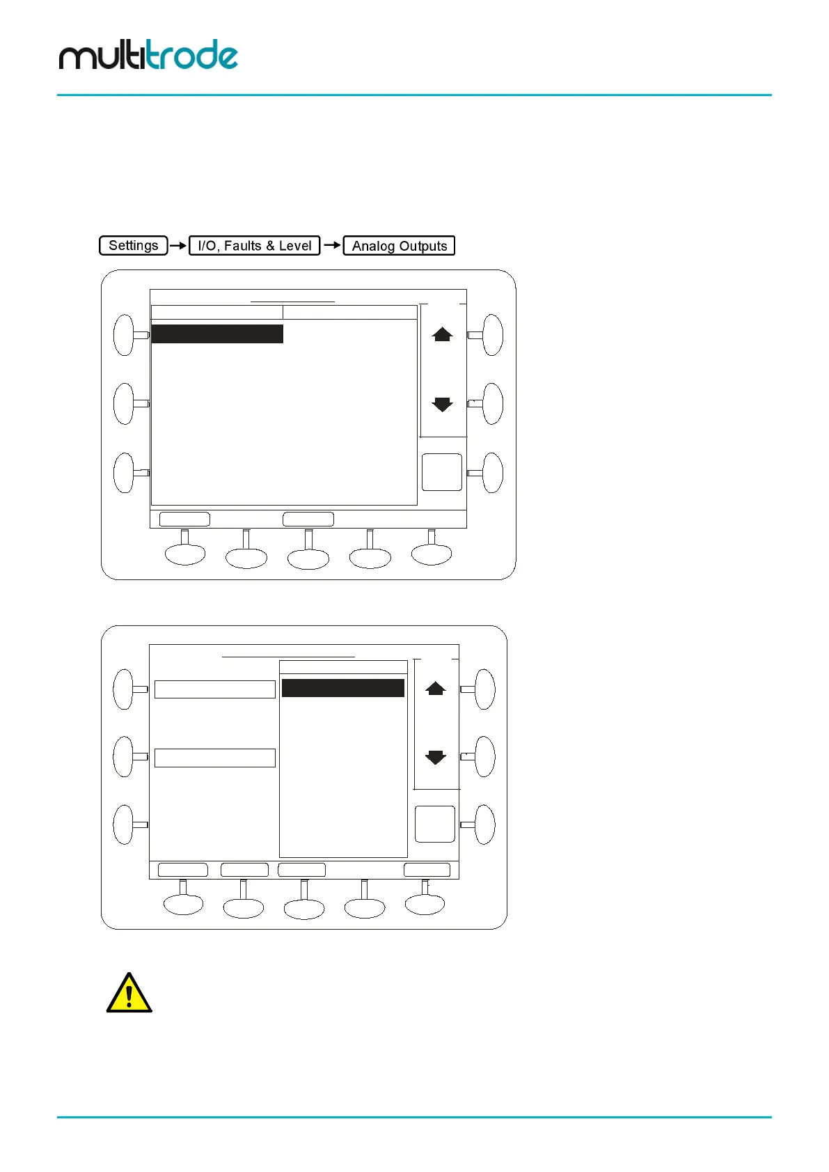
Analog outputs are configured in the Analog Output screen.
TopBoard Aout 01 ***TopBoard AIN 1
BottomBoard Aout 11
BottomBoard Aout 12
BottomBoard Aout 13
Unassign
Analog Outputs
Select
Back
Analog Output Assigned
Config
Figure 124 – Analog Outputs Screen
Top Board AIN 1
Top Board AIN 2
Current Level
VFD Current Speed
Remote Source
Configure Analog Outputs
Input
Back
Output
Inputs
Select
AdvancedPgDn
PgUp
Source
TopBoard Aout 01
Top Board AIN 1
Figure 125 – Select the source Analog Input and press “Select”
NOTE: By default, AOUT1 on the main 3PC board follows primary level
Page 130 of 260 MultiSmart_IO_Manual_R20