MultiSmart Installation & Operation Manual
7.3.3 Digital Volt-Free Outputs
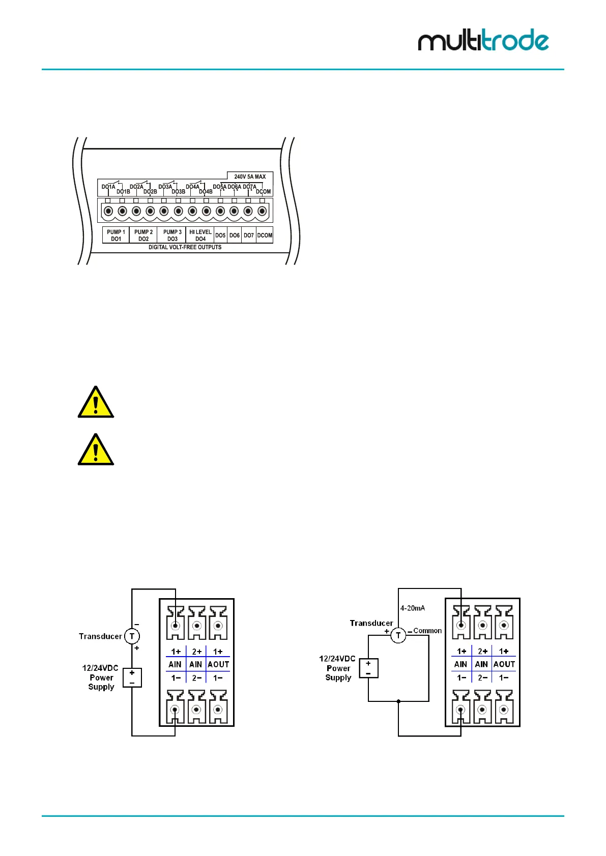
The pump control I/O board has seven 240V, 5A, and digital volt-free outputs:
Figure 44 – Digital Volt-free Outputs
• DO 1-4 – Isolated voltage free contacts
• DO 5-7 – Common rail voltage free contacts
• Multiple sources can be assigned to a digital output with the option of AND, OR and XOR
operations performed on the source
DO1-4 are configured by default if 3 pumps were selected during the Setup Wizard. For a
system which has less than 3 pumps, only the relevant digital outputs are configured. (For 4
pumps or more, no digital outputs are configured).
NOTE:
MultiTrode recommends that snubbers are fitted to the contactor coils that the digital outputs
are driving.
7.3.4 Analog Inputs
The pump control board has two isolated 4-20mA analog inputs.
• Maximum Load (Input Impedance) – 120 ohms
• Resolution 0.2%
• Isolated
Figure 45 – Analog Input –
External Excitation: 2-Wire
Figure 46 – Analog Input -
External Excitation: 3-Wire
MultiSmart_IO_Manual_R20 Page 47 of 260