MultiSmart Installation & Operation Manual
7.3.2.2 10 Sensor Probe (or Ball Floats)
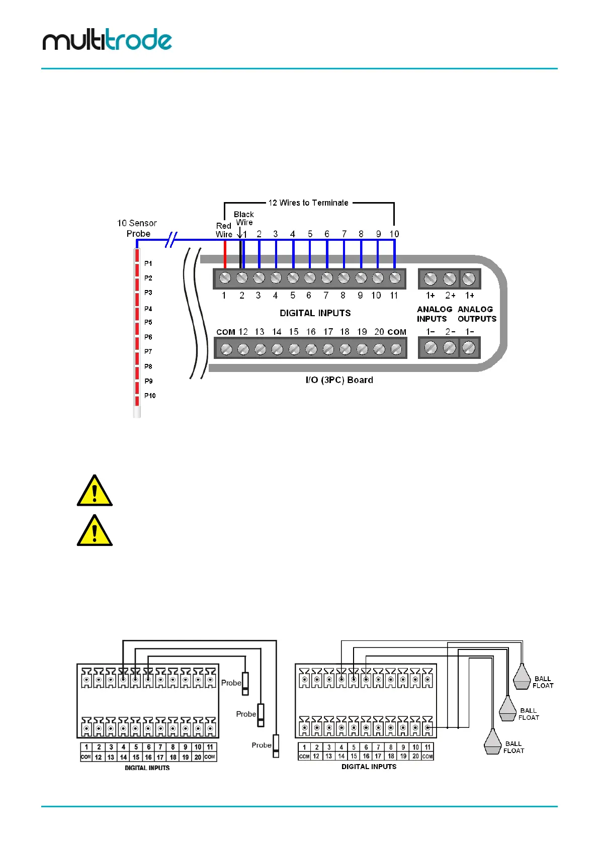
An example on how to connect a 10 sensor MultiTrode probe utilizing a 12 core cable is shown below.
Connect the 10 sensors from DI 2 to DI 11 (this matches the MultiSmart default configuration). To DI 1
connect the red wire. (While this input is reserved for the Failsafe function, if it is not required then DI 1 can
be used like any other digital input). The 12
th
core is black and is connected to DI 2 – thus forming a wire
loop from DI 1 through the probe cable, through the probe itself and back to DI 2. Periodically the MultiSmart
tests this loop for conductivity.
Figure 41 - 10 Sensor Probe Connections
For further Probe configuration information including DuoProbe connections, refer to Section 14.8.
NOTE:
The Fail Safe feature requires a compatible probe and firmware version 2.2.2 or later.
NOTE:
If more than one Fail Safe probe is installed, only one (1) Failsafe probe (the highest) is connected
to the Fail Safe input.
7.3.2.3 Single Sensor Probe (or Ball Floats)
An example of wiring single sensor probes is shown below. Any input can be used as long as they have
been configured to accept a single sensor probe using the interface. (See Section 14.8.4 - Single Sensor
Mode for more information).
42 – Single Sensor Inputs
Figure 43 – Ball Floats
Page 46 of 260 MultiSmart_IO_Manual_R20