MultiSmart Installation & Operation Manual
7.6.3 Current Inputs
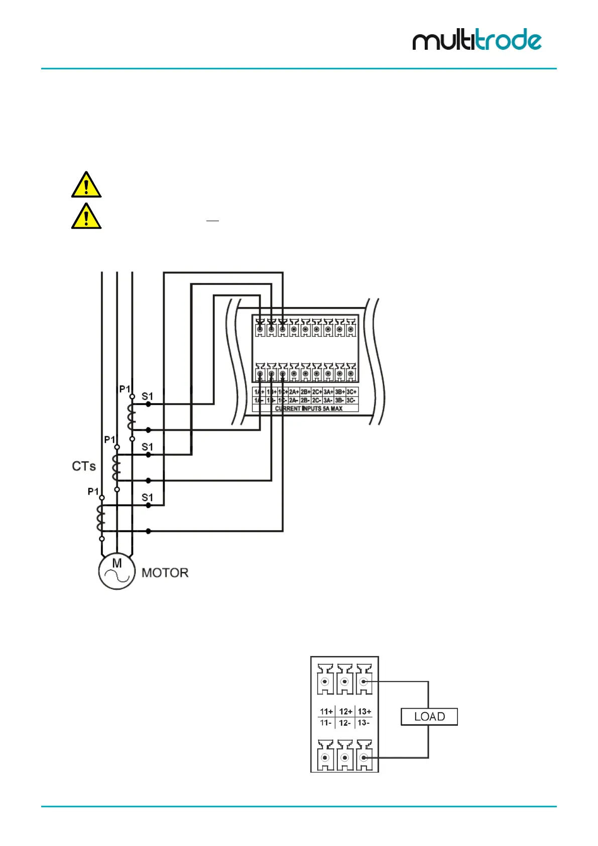
The Energy Monitoring and Motor Protection Board has three sets of three-phase current inputs. These
inputs measure between 0 - 5A and are connected to the secondaries of external CTs to measure higher
currents. The CTs must be wired with the correct polarity and ensure that the current phase corresponds to
the voltage phase. Shielded twisted pair cable is recommended between the CTs and MultiSmart. The shield
ground can be connected at either the MultiSmart end or at both, the MultiSmart and the CT, depending on
the predominate interference – electrical or magnetic.
NOTE: If the CTs are wired such that the polarity is wrong, the current reading will be correct, however
the power and energy calculations will be incorrect as the power factor will be zero.
NOTE: The CTs must not be grounded / earthed. Otherwise incorrect current readings will be measured.
When selecting CTs, consider the MultiSmart input resistance (around 40mΩ) and the resistance of the
copper wire used in the installation. To avoid losing accuracy of the current readings, do not burden the CTs.
Figure 62 – Current Inputs per Motor
7.6.4 Analog Output
The energy monitoring/motor protection board has 3 analog outputs which produce a 4-20mA output signal.
• Maximum Load (Impedance) – 800 ohms
• Resolution 0.2%
• Non-isolated
Figure 63 – Analog Output
MultiSmart_IO_Manual_R20 Page 57 of 260