2. Specifications
— 2-26 —
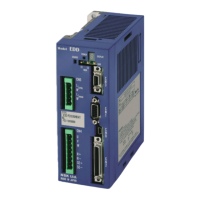
Table 2-12: Specifications of Driver Unit Model EDD (PN Series/PX Series)
Single phase 100 to 240 [VAC] 50/60[Hz]
Voltage Fluctuation: ±10/15[%] or less
Single phase 200 to 240 [VAC] 50/60[Hz] Voltage Fluctuation:
±10/15[%] or less
Position sensor resolution
[count/revolution]
Maximum velocity speed [s
-1
]
Program operation (256 program channels), Pulse train command, RS-232C serial communication
command, Jogging, Home Return
RS-232C serial communication command, Analog input command
RS-232C serial communication command, Analog input command
Photo coupler input. Maximum frequency 2 Mpps
Input format: CW/CCW, Pulse & direction or øA/øB
Resolution changer for free manipulation is available. (1000 to 5 242 880 [count/revolution])
Analog command voltage input voltage ±10 [V]
Photo coupler (± common), 17 input ports. Input voltage: 24 VDC
Emergency stop, Alarm clear, Over travel limit + direction, Over travel limit – direction, Servo ON, Program
operation start, Stop, Internal program channel switching 0 to 7, Jog, Jog direction, (Hold, Velocity override,
Integration OFF, Home Return start, and Home position limit)
*2
Signal format: øA/øB/øZ line driver. Free resolution setting to øA/øB is available.
Resolution of øA/øB: Shipping set: 20 480 [count/revolution] (Quadrupled: 81 920)
Maximum: 1 310 720 [count/revolution] (Quadrupled: 5 342 880)
*Because the maximum frequency is 781 [kHz], the setting of the resolution limits the maximum
rotational speed. (Max. velocity = 781 [kHz] / resolution of øA (øB)
Resolution of øZ: 80 [count/revolution]
Photo coupler (± common), 8 output ports. Max. switching capacity: 24 VDC/50 [mA]
Driver Unit ready, Warning, Travel limit detection + directions, Servo state, Busy, In-position, Target
proximity A (Target proximity B, Zone A•B•C, Travel limit +/- directions, Normal, Position error under/over,
Velocity under/over, Torque command under/over, Thermal loading under/over, Home Return complete,
Home position defined)
*2
Excess error, Program error, Automatic tuning error, Position command/Position feedback error, Software
thermal error, Home position undefined, Main AC line under voltage, Over travel limit, RAM error, ROM
error, System error, Interface error, ADC error, Emergency stop, CPU error, Position sensor error, Absolute
position error, Motor cable disconnected, Excess velocity, Commutation error, Overheat, Main AC line over
voltage, Excess current, Control AC line under voltage, Power module error
Analog monitor ×2, (Free range and offset setting), RS-232C/USB monitor
RS-232C serial communication (Asynchronous, 9600 bps), USB (USB2.0 compatible)
EEPROM (Overwriting and deleting of parameters are limited to 100 000 times.)
Automatic tuning
Function set to Input/Output ports available
Temporal parameter setting by program is available
Individual acceleration/deceleration setting
Acceleration profiling (deformation sine, deformation trapezoid, cycloid, simple harmonic)
Environ-
mental
conditions
Operating temperature /
storing temperature
0 to 50[°C] / -20 to 70[°C]
Operating humidity /
storing humidity
90% or less. No condensation.
Optional regeneration resistor available when the regeneration energy is beyond 28[J]. • Connect to
R+, R-, SE+ and SE-. (Never short-circuit them.)
Functions at power-off, servo-off and an occurrence of alarm.
Brake can be released by command (refer to "9.3.Glossary of Command and Parameter " command KB)
Compatible
safety
regulation
Half pitch connector 50 pins
Half pitch connector 14 pins
Motor/ optional
regeneration
resister
Control / main
power source
*1: Depends on the Motor type. Refer to “2.5 Motor Specifications.”
*2: Change of function assignment of the Input/Output ports will make these functions effective.
*3: The displayed numerical values are a combination with the Driver Unit power voltage 200 [VAC] / 100 [VAC].

 Loading...