Home
NSK
Media Converter
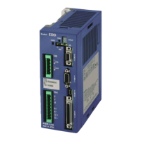
EDD Megatorque Motor
Page 55 (CN2 Interfacing)
NSK EDD Megatorque Motor - CN2 Interfacing; General Input Signal
398 pages
Manual
To Next Page
To Next Page
To Previous Page
To Previous Page
Loading...
2
.
Specificatio
ns
—
2-
33
—
2.10.2.
CN2 Interfacing
2.10.2.1.
General Input Si
g
nal
Applied inputs: SVON,
EMST, OT
P, ACLR, PRG0 to PRG7, JOG, DIR
, and STP
Table 2-
20
: Gen
eral specifications
Item
Specification
Input voltage
24 VDC ± 10%
Input impedance
3.9 k
Maximum current
10 mA or less (per input)
Fig 2-
35
: General specifications
3.
9k
Ω
56
0
Ω
Drive Unit side
※
DC24
Input
*
You may reverse the polarity of the exter
nal
power
supply and connect as
“minus
•
comm
on.”
54
56
Table of Contents
Main Page
Default Chapter
13
Table of Contents
13
1 Introduction
17
Notes to Users
18
Notes for Safety
18
Precautions for Use
18
Interchangeability of Motor and Driver Unit
21
Terminology
22
2 Specifications
23
System Configuration
23
Control Mode
23
Examples of System Configuration
24
Reference Number and Coding
26
Mega Torque Motor
26
Driver Unit Model EDD
26
Cable Set
26
Handy Terminal
26
Name of each Part
27
Mega Torque Motor
27
PS Series
27
PN Series
28
PX Series
29
Driver Unit Model EDD
30
Handy Terminal
31
Standard Combination List
32
Motor and Driver Unit Model EDD Combinations
32
Cable Set
33
Handy Terminal
33
Motor Specifications
34
PS Series
34
PN Series
35
PX Series
35
Axial Load and Moment Load
36
External Dimensions
37
Megatorque Motors
37
PS Series
37
PN Series
41
PX Series
43
Driver Unit Model EDD
44
Cable Set
45
Flexible Cable
45
Stationary Cable
45
Driver Unit Specifications
47
USB Interface Specifications
49
CN0: USB Communication Connector
49
CN0 Signal List
49
Pin-Out (CN0)
49
RS-232C Interface Specifications
50
CN1: RS-232C Serial Communication Connector
50
CN1 Pin-Out
50
CN1 Signal List
50
Specifications of Control Input/Output Interface2-29
51
CN2: Control Input/Output Signal Connector
51
CN2 Pin-Out
52
CN2 Signal List
53
CN2 Interfacing
55
General Input Signal
55
Pulse Train Input Signal
56
Analog Command Input Signal
57
Output Signal
58
Position Feedback Signal Output
58
Analog Monitor Output
59
CN3: Resolver Cable Connector
60
CN3 Pin-Out
60
CN3 Signal List
60
CN4: Motor Connector
61
CN4 Pin-Out
61
CN4 Signal List
61
CN5: Connector for Power Supply
62
CN5 Pin-Out
62
CN5 Wiring Diagram
62
3 Unpacking, Installation and Wiring
63
Unpacking
63
Receiving Check
63
Motor and Driver Unit Model EDD Combinations
63
Installation
64
Motor Mounting
64
Environmental Conditions of Motor
64
Motor Installation
64
Coupling Load to Motor
65
Confirmation of Use Conditions
66
Dummy Inertia
66
Installation of Driver Unit
67
Wiring
68
Connection of Cable Set
68
Connecting Power
69
Ground Connection
70
Connector Wiring
71
Wiring Example (CN2)
71
Turning on Main Power
72
Precautions before Power-On
72
Points to be Checked When Power-On
73
Polarity Setting of Control Input Port (Normally Open Contact and Normally Closed Contact)
74
Power on and Servo on
75
4 RS-232C Communication and USB Communication
77
RS-232C Communication (Handy Terminal Communication)
78
Check on Handy Terminal
79
Setting Parameters
79
Input of the Password
79
Reset to Shipping Set
80
Readout of Parameter
80
Monitoring Parameters Altered from Shipping Set
81
Monitoring Parameters by a Group
81
Monitoring the Current Status
82
Inputting a Command While
82
USB Communication (EDD MEGATERM)
83
Setting Application Software
85
Establishing Communication
86
Setting Parameters
86
Input of the Password
87
Reset to Shipping Set
88
Readout of Parameter
88
Monitoring Parameters by a Group
89
Monitoring Parameters Altered from
90
Monitoring the Current Status
90
Inputting a Command While
91
5 Tuning
93
Tuning Flowchart
93
Tuning Level 1: Automatic Tuning
94
Precautions for Automatic Tuning
95
Initialization of Servo Parameters
96
Automatic Tuning
97
Trial Running
99
Tuning Level 2: Servo Gain Tuning
101
Input of Load Moment of Inertia
101
When the Load Moment of Inertia Is
101
Minor Tuning of Servo Gains
102
Tuning Level 3: Manual Tuning
105
Precautions for Manual Tuning
105
Setting Velocity Loop Proportional Gain (VG)
105
Setting Filters (Tuning Level 2)
107
Setting Low-Pass Filter
107
Setting Notch Filter
108
6 Operation
109
Preparation
109
Wiring Check
109
Operation Procedure
109
Position Scale
110
Resolution of Position Scale
110
Direction of Position Scale
111
Setting Home Position
112
Software over Travel Limit
114
Setting the Limits by Teaching
115
Setting the Limits by Direct Input
116
Positioning Operation
117
Positioning Command
117
Program Positioning Operation
118
Program Operation Via Control Inputs and Outputs
119
Program Positioning Operation Via RS-232C Communication
121
Programming
122
Program Sequence
128
Pulse Train Command Positioning Operation
131
Format of Pulse Train Input
133
Operation
134
Resolution of Pulse Train --------------
134
Jogging with Control Input and Output
137
RS-232C Communication Positioning Operation -----------------------------------------
139
Velocity and Torque Control by Analog Input
141
Selection of Control Mode
141
RS-232C Communication Operation
142
Analog Input Operation
143
Analog Command Input Offset
144
7 Operational Function
147
Control Input
147
Emergency Stop: EMST
147
Alarm Clear: ACLR
148
Hardware over Travel Limit: OTP and OTM
149
Servo On: SVON
150
Channel Selection: Input PRG0 to PRG7
152
Stop: STP
153
Jogging: JOG Jogging Direction: dir
155
Control Output
156
Driver Unit Ready: DRDY
156
Warning: WRN
156
Over Travel Limit Direction: OTPA and OTMA
157
Servo State: SVST
159
In-Operation: BUSY
160
In-Position: IPOS
161
CFIN Mode: Parameter FW
162
IPOS Mode (Parameter FW = 0)
163
FIN Mode (Parameter FW > 0)
164
In-Position Limit: Parameter in
165
Parameter IS
165
Target Proximity: NEARA and NEARB
166
Position Feedback Signal
167
Resolution of Position Feedback Signal
168
Signal Output Timing
170
RS-232C/USB Monitor
171
Monitoring Way for Control Input/Output Signal
172
Electrical Condition Monitor: Monitor IO0
173
Monitor for Internal Recognition of Input and Output State: Monitor IO1
174
Monitor for State of Input Functions
174
Monitor for Individual Function
175
Monitor for State of Output Functions: Monitor IO3
175
Alarm Monitor
176
Monitor All Occurring Alarms at
176
Monitor for Alarm History and Event: Monitor TA/HI
177
Pulse Train Counter: Monitor RP
178
Position Feedback Signal Counter: Monitor FK
178
Current Position Monitor: Monitor TP
178
Monitor TJ
179
Analog Monitors
180
Use of Preset Monitors
181
Customization of Monitor Data
182
Analog Monitor for State of Control Inputs and Outputs Functions
183
8 More Advanced Function
185
Assignment of Input/Output Function
185
Function of Control Input
186
Function of Control Output
188
Editing Function of Control Input and Output
190
Editing Control Input Function
190
Editing Control Output Function
192
Masking Control Output Function
194
Forcible Output in Setting of Output Port Function
195
Extended Control Input
196
Input HOLD: HLD
196
Velocity Override: ORD
197
Integration OFF: IOFF
198
Home Return Start: HOS
199
Home Position Limit: HLS
199
Extended Control Output
200
In-Zone Output: ZONEA, ZONEB, and ZONEC
200
Outputs of Operating Conditions
201
Position Error: TEU (Position Error, under and TEO (Position Error, Over) -----------
202
Torque Command: Outputs TTU
203
Velocity: Outputs TVEU (Velocity Error,Under and TVEO (Velocity Error, Over) -------
203
Thermal Loading
204
Travel Limit Output (±): OTXA
205
Output Normal: NRM
206
Home Return Completed: HOME
206
Home Position Defined: HCMP
206
Teaching
207
Preparation for Teaching
208
Teaching of Parameter
208
Teaching the Position Data of Positioning Program
209
Tuning
210
Servo Block Diagram
210
Digital Filter
212
Position Loop Dead Band
213
Automatic Gain Switching
214
Positioning Operation
215
Acceleration Profiling and Individual
215
Examples of Acceleration Profiling and Individual Setting of Acceleration and Deceleration
217
Shorter Way Positioning
218
User Scale Positioning
220
Program Operation
223
Change of Parameter Via Program Operation
223
Automatic Program Execution at Power on
225
Home Return
229
Home Return Operation Via the Home Position Sensor
230
Home Return Mode: OS4
230
Home Return Mode: OS1
232
Home Return Mode: OS3
232
Home Return Mode: OS5
232
Home Return with Travel Limit
233
Home Return Mode: OS7
233
Teaching of Home Position
235
Home Return Mode: OS6
235
Teaching of Home Position in Servo-Off Sate
236
Position Adjustment of Home Limit Sensor
237
Teaching of Home Position Offset
238
RS-232C Communication
239
Specifications of Communication
239
Communication Procedure
239
Power on
240
Command Entry
241
Cancelling Command
242
Input of the Password
242
Readout of Parameter Settings and Internal State
243
Reading out Parameter Settings by a Group
244
Error Message
245
9 Details of Command and Parameter
247
Difference of RS-232C Communication and USB Communication
247
Different Commands between RS-232C Communication and USB Communication
247
Simultaneous Operation of RS-232C Communication and USB Communication
247
Command Parameters Invalid in USB Communication
247
Inhibited Operations in USB Communication
248
Handling Instruction of Command and Parameter
249
Character String of Command
249
Grammar of Command
249
Error Message
250
Multi-Statement on a Line
250
Wildcard Search
251
Repeating Readout
251
Multi-Monitor
252
Initialization of Specified Parameter
252
Adjusting
253
Output to Analog Monitor
253
Glossary of Command and Parameter
254
Parameter List
330
10 Maintenance
333
Backup Parts
333
Storing the Parts
333
Periodic Check
334
Motor
334
Driver Unit (Including Cables and Handy Terminal)
334
Periodic Replacement of Parts
335
Motor
335
Cables
335
Driver Unit
336
Repair Service
338
Warranty Period and Covering Range
339
Warranty Period
339
Limited Warranty
339
Immunities
339
Service Fee
339
Notice for Discontinuity of the Product and Duration of Support
339
Application to Special Uses
339
11 Alarm and Warning
341
Identifying Alarm and Warning
341
LED Alarm Indicator
341
Confirmation of Alarm and Warning
342
History of Alarm and Warning
343
List of Alarm and Warning
345
Normal State
345
Condition in the State of Alarm and Warning
346
Alarm
346
Over Travel Limit
347
Warning
347
Cause and Remedy
348
CPU Error
348
Alarm A0: Disconnected Sensor Cable
348
Alarm A1: Position Data Error
349
Alarm A2: Motor Cable Disconnected
349
Warning A3: Software Thermal
350
Alarm A4: Excess Velocity
351
Warning A5: Home Position Undefined
351
Alarm A9: Commutation Error
352
Warning C0: Position Command/Feedback Signal Error
353
Alarm C3: CPU Error
353
Alarm E0: RAM Error
354
Alarm E2: ROM Error
354
Alarm E7: System Error
355
Alarm E8: Interface Error
355
Alarm E9: ADC Error
355
Warning F1: Excess Position Error
356
Over Travel F2: Software over Travel Limit
357
Over Travel F3: Hardware over Travel Limit
358
Alarm F4: Emergency Stop
359
Warning F5: Program Error
359
Warning F8: Automatic Tuning Error
360
Warning P0: over Heat
361
Alarm P1: Main Power Overvoltage
361
Alarm P2: Motor over Current
362
Alarm P3: Control Power under Voltage
362
Warning P5: Main Power under Voltage
363
Alarm P9: Power Module Alarm
363
12 Troubleshooting
365
Identifying Problem
365
Power Trouble
366
Motor Trouble
366
Vibration, Abnormal Noise or Unstable Settling
367
Improper Positioning
367
RS-232C Communication Problem
368
Appendix 1
369
Appendix 1: How to Monitor Input and Output Signal
369
Appendix 2: How to Check Motor Condition
374
Appendix 3: How to Back up and Restore the Settings
378
Appendix 4: Handling of Saved Data in Megaterm
386
Driver Unit Model EDD
388
Appendix 5: Procedure for Replacing
390
Appendix 6: Regeneration Resistor
390
Appendix 7: Wiring of RS-232C Communication Cable
392
Appendix 8: USB Communication Cable
393
Appendix 9: Setting List of Parameter and Program of
394
Driver Unit Model EDD
397
Related product manuals
NSK Varios 370
46 pages
NSK Varios 170
52 pages
 Loading...