3. Unpacking, Installation and Wiring
— 3-11 —
3.4.2. Points to be Checked When Power-on
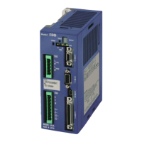
(1) Turn on the power and confirm that the LED on the front panel indicates the normal state of the System.
Fig 3-9: When error occurs
Fig 3-10: In normal state
Power LED: It tuns on when the pwoeris on.
Normal state: Green
Error occurs: Orange
7segments LED: Identifies a type of alarm.
It indicates a type of alarm in 2 digit
numbers. The numbers will be
dispalyed in time sharing.
If two or more errors occurs, the LED
indicates them in the same manner as
described above.
Power LED: Turns on when the power
turns on.
• Normal state: Green • Error: Orange
(2) Check if the Emergency stop (CN2, pin #3: EMST) input is effective.
• When the emergency stop input is ON, the 7 segments LED on the front panel indicates the alarm
code in the order of F → 4 If not, refer to “11. Alarm and Warning”
Warning : The shipping set of the EMST input (EMST) is a normally closed contact.
If it is not connected, the alarm F4 (Emergency stop) occurs. Wire the
EMST circuit or change the polarity to a normally open contact referring
to “3.4.3. Polarity Setting of Control Input Port” to clear the alarm.
Warning : The shipping set of the inputs OTP and OTM (Over travel limit) are the
normally closed contact. It will cause an alarm if they are not connected.
Wire them or change the polarity to the normally open contact referring to
“3.4.3.Polarity Setting of Control Input Port” to clear the alarm.
(3) The System is in the normal state when the display of the Handy Terminal shows the prompt
“: (colon)” after the message of “NSK MEGATORQUE.”
Fig 3-11: Indication of the display of the Handy Terminal
NSK MEGATORQUE
XSY*****.*,XOP*
DD1DA0_*****.*
:_
The part represented by (*) depends on
the System type.
 Loading...