4.1. Quick Troubleshooting…Alarm when the power is on
The alarm occurs when the power is turned on if input signals of EMST (Emergency stop, Pin No.3) and OTP/OTM
(Over travel limits, Pin No. 5 and 6) of the connector CN2 are not connected.
However, the Driver Unit is not defective.
◊ This is because the ports of EMST input and OTP/OTM inputs are set to the normally closed contact (B contact) at the
factory.
To cancel the alarm, wire these ports or follow the procedure below to change the polarity to the normally open contact
(A contact).
Step 1: identify the alarm.
1) Turn on the power of the Driver Unit.
2) Check the 7 segments LED on the front panel of the Driver Unit.
◊ The LED changes in order of F → 4 in case of “Emergency stop.”
◊ The LED changes in order of F → 3 in case of “Travel limit over” alarm.
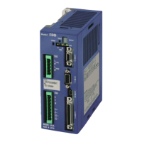
Power LED:Turns on after the power is on. .
Normal: Green
Abnormal: Orange
7segments LED: Identifies a type of alarm.
It indicates a type of alarm in 2 digit
numbers. The numbers will be dispalyed in
time sharing.
If two or more errors occurs, the LED
indicates them in the same manner as
described above.
Powe LED: Turns on after the power is on.
Normal: Green
Abnormal: Orange
 Loading...