6 I/O Memory Areas
6-10
CJ2 CPU Unit Software User’s Manual
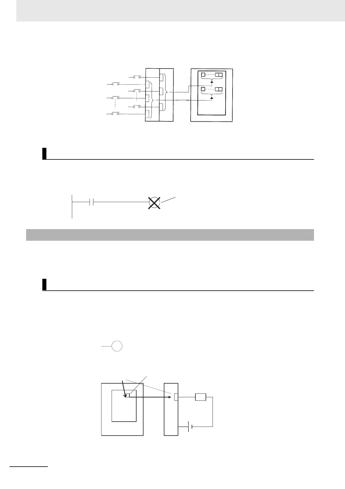
In the following example, the status of input points allocated to CIO 0 and CIO 1 are read from the
Input Unit. (CIO 2 and CIO 3 are allocated to Output Units.)
There is no limit on the number of times that input bits can be used as normally open and normally
closed conditions in the program. The addresses can be programmed in any order.
An input bit cannot be used as an operand in an OUTPUT instruction.
A bit in the I/O Area is called an output bit when it is allocated to an Output Unit. The ON/OFF status of
output bits are output to devices such as actuators. There are three ways for the status of output bits to
be refreshed to an Output Unit: normal I/O refreshing, immediate refreshing, and IORF(097) refreshing.
The status of output bits are output to external devices once each cycle after program execution.
In the following example, CIO 2.01 is allocated to an actuator, an external device connected to an
output terminal of an Output Unit. The ON/OFF status of CIO 2.01 is output to that actuator once
each cycle.
Restrictions on Input Bits
6-2-2 Output Bits
Normal I/O Refreshing
Input Unit CPU Unit
Read
when
IORF
(097)
is
execu-
ted.
Switch 0
Switch 1
Switch 15
Switch 16
Switch 17
Switch 31
0.01
1.00
Not allowed if CIO 1.00 is an input bit.
2.01
OUT 2.01
CIO 2.01
Ladder symbol
Mnemonic
CPU Unit
Bit allocation
Output Unit
Actuator
Once
each
cycle