2-3
2 Internal Memory in the CPU Unit
CJ2 CPU Unit Software User’s Manual
2-1 Overview
2
2-1-2 Memory Areas and Stored Data
Precautions for Correct UsePrecautions for Correct Use
The following will occur if the battery is low or when no battery is installed.
• Data in the I/O memory areas will be lost or values will become unstable, including values in
the DM, EM, and HR Areas, which are retained by the battery when power is OFF.
• The clock will stop, and all clock-related data will become unstable.
• Error logs will not be retained.
• The Output OFF Bit will become unstable.
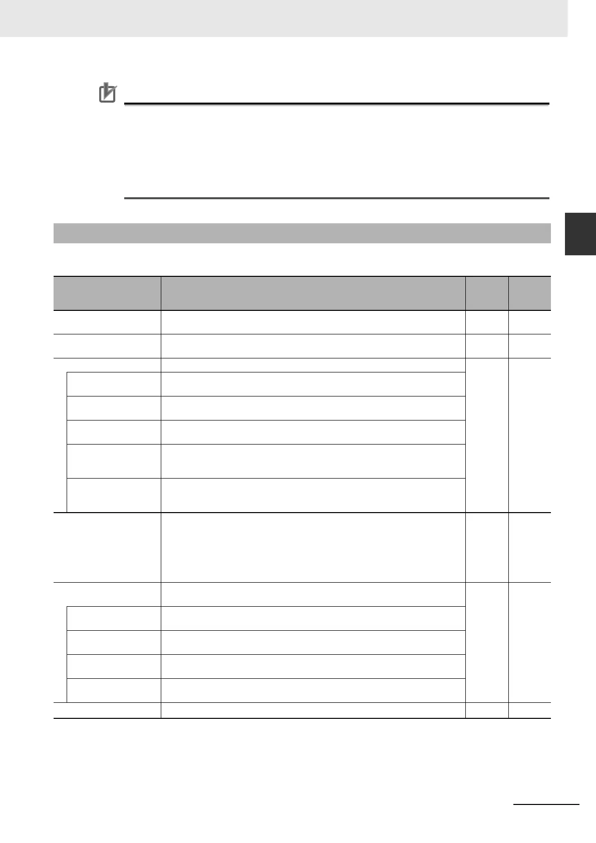
The following table lists the CPU Unit memory areas and the data stored in each area.
*1 Supported only by the CJ2M CPU Units. With CJ2H CPU Units, function block definitions are stored in the User Program
Area instead of the FB Program Area.
*2 Supported only by the CJ2H-CPU6@-EIP and CJ2M-CPU3@.
2-1-2 Memory Areas and Stored Data
Memory area and stored
data
Details
Built-in
flash
memory
Built-in
RAM
User Program Area The User Program Area stores the object code for executing the user program that
was created using the CX-Programmer.
Stored. Stored.
FB Program Area
*1
The FB Program Area stores the function block definitions created using the CX-
Programmer.
Stored. Stored.
Parameter Area The Parameter Area stores the initial settings for the PLC. Stored. Stored.
PLC Name The name of the CPU Unit is stored and can be read and verified by the CX-Pro-
grammer to prevent the CX-Programmer from connecting to the wrong PLC.
PLC Setup Various initial settings are made in the PLC Setup using software switches. Refer to
Section 9 PLC Setup.
I/O Tables I/O tables provide information on the mounting status of Units specified by the user.
Refer to Section 8 I/O Allocations and Unit Settings.
Routing Tables Routing tables are network parameters for FINS communications. They are speci-
fied using the CX-Integrator. Refer to the CX-Integrator Operation Manual (Cat. No.
W464).
CPU Bus Unit Setup The CPU Bus Unit Setup stores the initial settings for specific CPU Bus Units. It
includes settings such as Ethernet settings for Ethernet Units and data link parame-
ters for Controller Link Units.
I/O Memory Areas The I/O Memory Areas are used for reading and writing from the user program. It is
partitioned into the following regions according to purpose.
A region where data is cleared when power to the CPU Unit is reset, and a region
where data is retained.
A region where data is exchanged with other Units, and a region that is used inter-
nally.
--- Stored
Source and Comment
Areas
The Source and Comment Areas are used for storing the program source code and
comments created using the CX-Programmer.
Stored ---
Source Code The source code for programs (in tasks and function blocks, using ladder, ST, and
SFC languages).
Symbol Table The symbol table contains symbols created using the CX-Programmer (symbol
names, addresses, and I/O comments).
Comments Comments are created using the CX-Programmer and include annotations and row
comments.
Program Index The program index provides information on program sections created using the CX-
Programmer, as well as program comments.
Network Symbols (Tags)
*2
Data for network symbols in the global symbol table. Stored ---