5 Understanding Programming
5-6
CJ2 CPU Unit Software User’s Manual
Ladder diagram logic is a basic language for PLCs that is written in a form that appears similar to elec-
trical circuits. Instructions are executed in the order they are recorded in memory (mnemonic order). It
is important that you correctly understand the basic programming concepts as well as the execution
order.
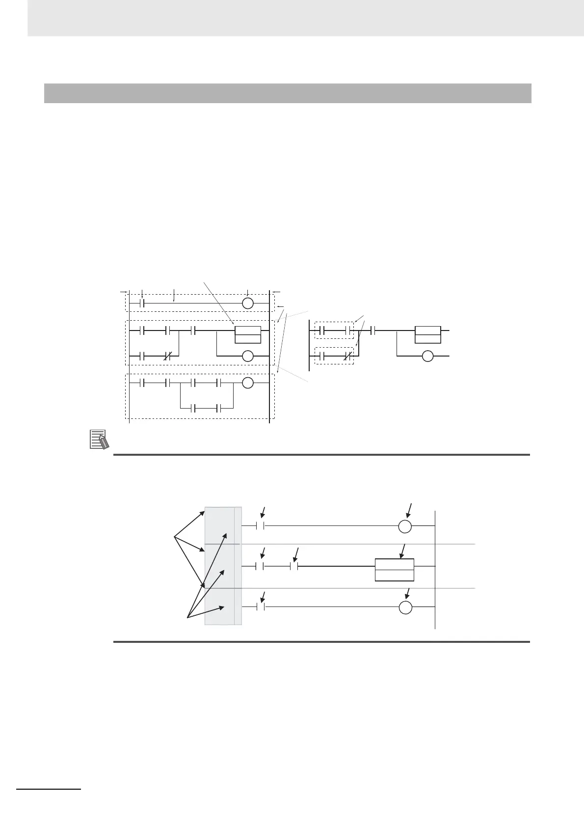
z General Structure of the Ladder Diagram
A ladder diagram consists of left and right bus bars, connecting lines, input bits, output bits, and spe-
cial instructions. A program consists of one or more program runs. A program rung is a unit that can
be partitioned when the bus is split horizontally. In mnemonic form, a rung is all instructions from a
LD/LD NOT instruction to the output instruction just before the next LD/LD NOT instructions. A pro-
gram rung consists of instruction blocks that begin with an LD/LD NOT instruction indicating a logical
start.
Additional Information
With the CX-Programmer, the rung number and first program address on each rung are dis-
played at the left of each rung.
5-1-2 Basic Ladder Diagram Concepts
Input bit
Connecting line
Output bit
Rungs
Left bus bar
Special
instruction
Right bus bar
Instruction blocks
0
0
1
2
2
5
1
2 3
4
5 6
Program address: 0
Rung number
First program address
on each rung