10-79
10 CPU Unit Functions
CJ2 CPU Unit Software User’s Manual
10-7 Debugging
10
10-7-10 Failure Point Detection
Precautions for Correct UsePrecautions for Correct Use
To clear fatal and non-fatal system errors simulated by executing FAL(006) and FALS(007)
instructions, use the same methods as for actual system errors. For information on how to clear
errors, refer to Section 6 Troubleshooting of CJ2 CPU Unit Hardware User’s Manual (Cat. No.
W472). All system errors simulated with FAL(006) and FALS(007) can be cleared by cycling the
power supply.
The FPD(269) instruction performs time monitoring and logic diagnosis. The time monitoring function
generates a non-fatal error if the diagnostic output isn't turned ON within the specified monitoring time.
The logic diagnosis function indicates which input is preventing the diagnostic output from being turned
ON.
FPD(269) starts timing when it is executed and turns ON the Carry Flag if the diagnostic output isn't
turned ON within the specified monitoring time. The Carry Flag can be programmed as the execution
condition for an error processing block. Also, FPD(269) can be programmed to generate a non-fatal FAL
error with the desired FAL number.
When an FAL error is generated, a preset message will be registered and can be displayed on the CX-
Programmer. FPD(269) can be set to output the results of logic diagnosis (the address of the bit pre-
venting the diagnostic output from being turned ON) just before the message.
The teaching function can be used to automatically determine the actual time required for the diagnos-
tic output to go ON and set the monitoring time.
FPD(269) determines which input bit is causing the diagnostic output to remain OFF and outputs that
bit's address. The output can be set to bit address output (PLC memory address) or message output
(ASCII).
If bit address output is selected, the PLC memory address of the bit can be transferred to an Index Reg-
ister and the Index Register can be indirectly addressed in later processing.
If the message output is selected, the bit address will be registered in an ASCII message that can be
displayed on the CX-Programmer.
10-7-10 Failure Point Detection
Time Monitoring Function
Logic Diagnosis Function
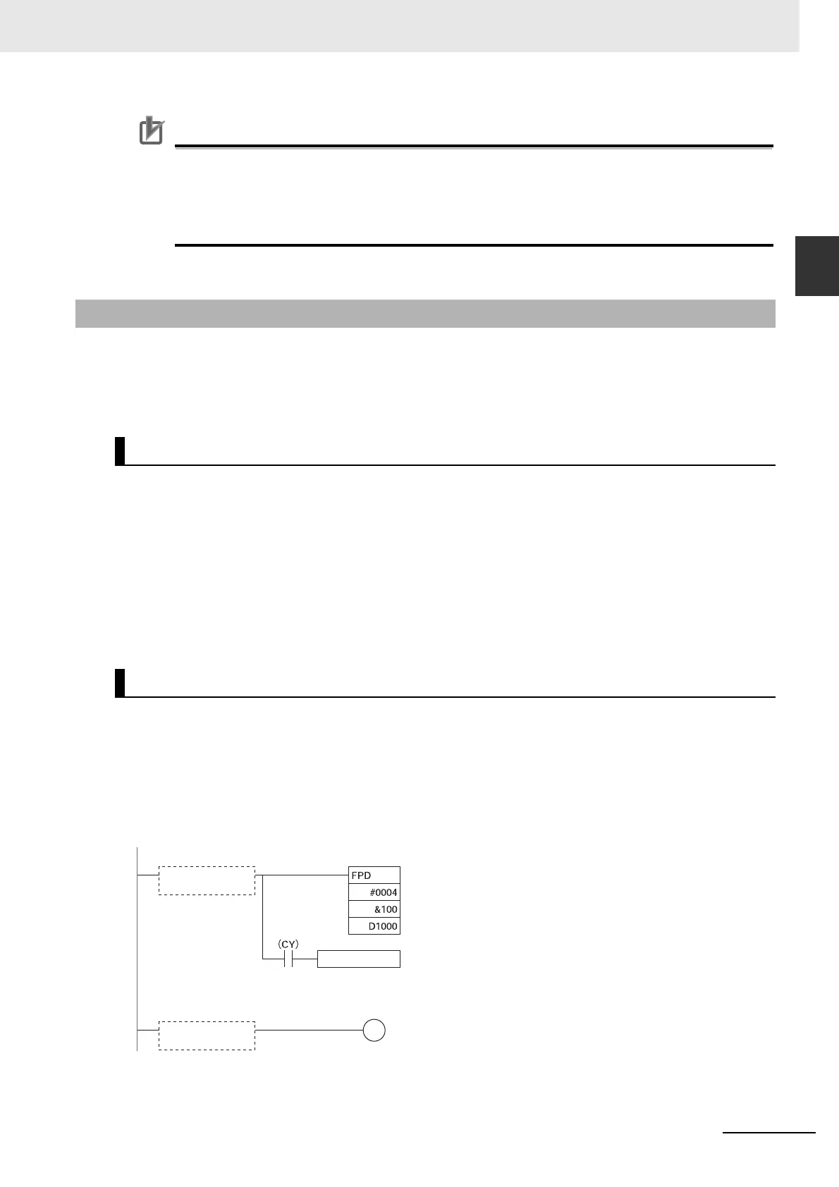
C (Diagnostic output)
Logic diagnosis
execution condition
B
Carry Flag
Error-processing block
Monitoring time (0.1-s units): 10 s
First register word (Diagnostics output destination)
FPD(269) execution
condition
A
Control data (FAL 004, logic diagnosis output: bit address output)