4 CPU Unit Initialization
4-16
CJ2 CPU Unit Software User’s Manual
4-6 CPU Bus Unit Setup Area
A setup area stores the settings for specific CPU Bus Units mounted to the CPU Unit. The following
three types of Units and settings use this area.
• Ethernet Units: Ethernet settings
• Controller Link Units: Data link tables (when user-set tables are used)
• FL-net Units: FL-net settings
Make the settings using the following Support Software.
The maximum amount of memory that can be used for the CPU Bus Unit Setup Area is 10,752 bytes.
Design the system so that the memory used for the CPU Bus Unit Setup Area is within the limit accord-
ing to the combination of CPU Bus Units in the PLC. If the limit is exceeded, some Units may operate
only at the default settings, and some may not operate.
z Memory Used for CPU Bus Unit Setup Area
Units that use 0 bytes do not use the CPU Bus Unit Setup Area.
4-6-1 CPU Bus Unit Setup Area
4-6-2 Setting Procedure
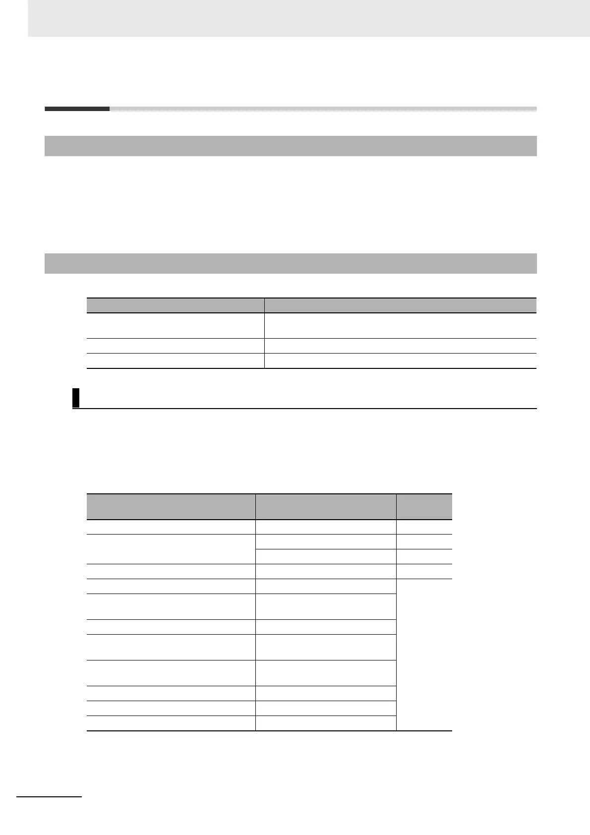
Data Support Software
Ethernet Unit settings Make the settings for the Special I/O Unit or CPU Bus Unit in the
I/O tables of the CX-Programmer or make the setting using HTML.
Controller Link Unit data link tables Make the settings using data link tables in the CX-Integrator.
FL-net Unit settings Make the settings using the CX-FLnet FL-net Support Software.
Memory Used for CPU Bus Unit Setup Area
Unit Model
Size used
(bytes)
Controller Link Unit CJ1W-CLK23 512
Ethernet Unit CJ1W-ETN11 412
CJ1W-ETN21 994
FL-net Unit CJ1W-FLN22 988
EtherNet/IP Unit CJ1W-EIP21 0
Serial Communications Unit CJ1W-SCU21/31/41-V1
CJ1W-SCU22/32/42
DeviceNet Unit CJ1W-DRM21
Position Control Unit with MECHA-
TROLINK-II Communications
CJ1W-NCF71 (-MA)
EtherCAT-compatible Position Control
Units
CJ1W-NC281/481/881/F81
CJ1W-NC482/882
Motion Control Unit CJ1W-MCH71
Analog Input Unit CJ1W-ADG41
Storage and Processing Unit CJ1W-SPU01-V2